Chrysler Le Baron, Dodge Dynasty, Plymouth Acclaim. Manual - part 89
WARNING: WHEN REMOVING THE REAR AXLE
PIVOT BUSHING ON VEHICLES EQUIPPED WITH EI-
THER REAR COIL SPRINGS OR AIR SUSPENSION.
THE REAR AXLE MUST BE SUPPORTED BY THE
AXLE AND TRAILING ARM TO ENSURE ADEQUATE
SUPPORT OF REAR AXLE.
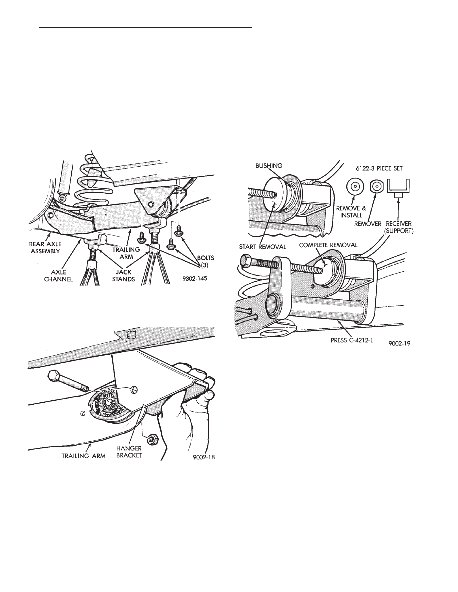
(3) Support the rear axle assembly at both the axle
channel and the trailing arm (Fig. 6). Then remove
lower shock absorber to rear axle mounting bolt (Fig.
6).
(4) Remove hanger bracket to frame rail bolts (Fig.
7).
(5) Lower axle assembly down enough to remove
pivot bolt and hanger bracket (Fig. 7). Right side
trailing arm shown.
PIVOT BUSHING REMOVAL FROM AXLE AS-
SEMBLY
Remove bushing with Remover/Installer Spe-
cial Tool C-4212-L (Press) and 3 piece set, Spe-
cial Tool 6122 (Receiver Support Bridge, Bushing
Remover/Installer and Bushing Remover).
(1) Install receiver (support) bridge into base of
press C-4212-L and bushing Remover/Installer disc
onto screw.
(2) Position assembly with receiver bridge support-
ing trailing arm while turning screw to begin bushing
removal.
(3) After bushing has begun to move replace bushing
remover/installer (round disc) with bushing remover
(oval shaped disc). Use this assembly to finish pressing
bushing out of trailing arm (Fig. 8).
PIVOT BUSHING INSTALLATION
(1) Align the bushing with the bushing mounting
hole in the trailing arm bracket (Fig. 9). Tap bushing in
slightly to hold position.
(2) Assemble bushing installer Tool onto press screw
and support bridge into press base. Position assem-
bly as shown in (Fig. 10) and press bushing into
arm to depth shown in (Fig. 9).
(3) Position hanger bracket on pivot bushing, and
install through bolt, loose assemble nut (Fig. 11). Right
side trailing arm shown.
(4) Position hanger to frame rail (a suitable drift will
aid in guiding hanger bracket into position). Install
and tighten screws to 75 N
Im (55 ft. lbs.) torque (Fig.
12). Install lower shock absorber mounting bolt, but
do not tighten.
(5) Position brake hose mounting bracket to trailing
arm, install and tighten retaining screw to 11 N
Im (95
in. lbs.) torque (Fig. 13).
(6) Attach park brake cable housing to hanger
bracket and cable to connector.
Fig. 8 Tools Installed To Remove Bushing
Fig. 6 Remove Pivot Bushing Hanger Bracket Bolts
Fig. 7 Remove Hanger Bracket
Ä
SUSPENSION AND DRIVESHAFTS
2 - 53