Chrysler Le Baron, Dodge Dynasty, Plymouth Acclaim. Manual - part 82


  Index      Chrysler     Chrysler Le Baron, Dodge Dynasty, Plymouth Acclaim - service repair manual 1993 year


Search            


Content   ..  80  81  82  83   ..


Chrysler Le Baron, Dodge Dynasty, Plymouth Acclaim. Manual - part 82


DRIVESHAFTS

INDEX

page

page

C/V Joint Boots Handling and Cleaning

. . . . . . . . 44

Damper Weights

. . . . . . . . . . . . . . . . . . . . . . . . . 48

Driveshaft Identification

. . . . . . . . . . . . . . . . . . . . 27

Driveshaft Positioning Specifications

. . . . . . . . . . 48

Driveshaft Reconditioning Procedure

. . . . . . . . . . 31

Driveshafts, Remove Install

. . . . . . . . . . . . . . . . . 27

General Information

. . . . . . . . . . . . . . . . . . . . . . . 25

Inner C/V Joint

. . . . . . . . . . . . . . . . . . . . . . . . . . 32

Intermediate Shaft Assembly Recondition

. . . . . . 41

Outer C/V Joint

. . . . . . . . . . . . . . . . . . . . . . . . . . 37

Service Procedures

. . . . . . . . . . . . . . . . . . . . . . . 27
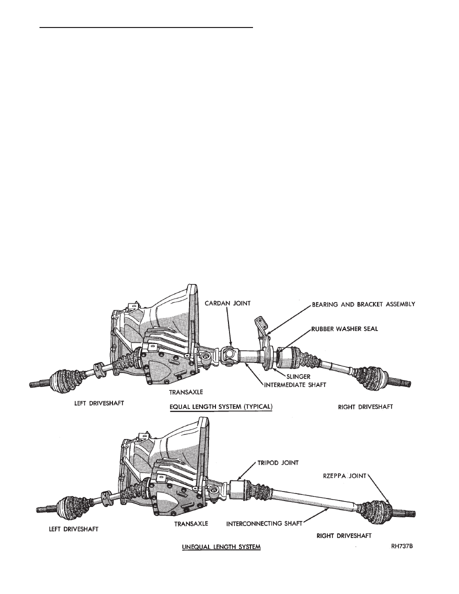
GENERAL INFORMATION

Chrysler front wheel drive vehicles use two different

driveshaft systems. Some vehicles use an equal length
system while other vehicles use an unequal length sys-
tem (Fig. 1).

The equal length system has short solid interconnect-

ing shafts of equal length on the left and right sides.
The unequal length system has a short solid intercon-
necting shaft on the left side with a longer tubular or
solid interconnecting shaft on the right.

The driveshaft assemblies can be serviced in the same

manner for both systems. With the exception of a rubber
washer seal attached to the right inner (Constant Veloc-

ity) C/V joint, on an equal length installation. The equal
length system also has an intermediate shaft attached to
a cardan joint (U-joint). With a stub shaft splined into
the right side of the transaxle with a bearing and
bracket assembly fastened to the right rear of the engine
block.

The driveshaft assemblies are three piece units. Each

driveshaft has a Tripod Joint, an Interconnecting Shaft
and a Rzeppa joint. The Tripod Joint is splined into the
transaxle side gear, or into the intermediate shaft on
the right side of an equal length system. The Rzeppa
joint has a stub shaft that is splined into the wheel hub.

Fig. 1 Front-Wheel-Drive Driveshaft Systems

Ä

SUSPENSION AND DRIVESHAFTS

2 - 25

Fig. 2 Driveshafts Identification (Halfshafts)

2 - 26

SUSPENSION AND DRIVESHAFTS

Ä

DRIVESHAFT IDENTIFICATION

Driveshafts are identified by the manufacturer. Vehi-

cles can be equipped with any of these driveshaft as-
semblies. Each assembly can be identified as shown in
(Fig. 2).

SERVICE PROCEDURES

Procedures for the removal and installation of the

driveshafts are essentially the same for all front
wheel drive vehicles. Each driveshaft has a spring
within the inboard Tripod C/V joint that maintains
constant engagement with the transaxle. This allows
the drive shaft to be removed without dismantling
part of the transaxle.

CAUTION: Boot sealing is vital to retain special lu-
bricants and to prevent foreign contaminants from
entering the C/V joint. Mishandling, such as allow-
ing the assemblies to dangle unsupported, pulling
or pushing the ends can cut boots or damage C/V
joints. During removal and installation procedures
always support both ends of the driveshaft to pre-
vent damage.

DRIVESHAFTS, REMOVE INSTALL

HUB NUT REMOVAL

Hub nut removal and installation is the same for

all front wheel drive vehicles. For installation see
Hub Nut Assemblies Install.

(1) Remove cotter pin, lock and spring washer (Fig.

3).

(2) Loosen hub nut and wheel nuts while vehicle is

on floor and brakes applied (Fig. 4).

(3) Raise vehicle, see Hoisting in Lubrication and

Maintenance, Group 0 of this service manual.

(4) Remove hub nut, washer, wheel and tire as-

sembly (Fig. 5).

DRIVESHAFT ASSEMBLIES REMOVE

Inboard C/V joints have stub shafts splined into the

differential side gears, or splined into the intermedi-
ate shaft on the right side of an equal length system.
Driveshafts are retained in the side gears by a con-
stant spring force provided by a spring contained
within the inboard C/V joints.

(1) For removal of right driveshaft, the speedome-

ter pinion must be removed BEFORE shaft removal
(Fig. 6).

(2) Remove clamp bolt securing ball joint stud into

steering knuckle (Fig. 7).

(3) Separate ball joint stud from steering knuckle

by prying against knuckle leg and control arm.

CAUTION: Do not damage ball joint or C/V joint
boots (Fig. 8).

(4) Separate outer C/V joint splined shaft from hub

by holding C/V housing while moving knuckle(hub)
assembly away (Fig. 9).

Fig. 3 Remove Cotter Pin, Nut Lock, & Spring

Washer

Fig. 4 Loosen Hub Nut & Wheel Nuts

Fig. 5 Remove Hub Nut & Washer Loosen Shaft

Ä

SUSPENSION AND DRIVESHAFTS

2 - 27

CAUTION: Do not pry on or otherwise damage wear
sleeve on outer C/V joint.

(5) Support assembly at C/V joint housings. Re-

move by pulling outward on the inner joint housing.

DO NOT PULL ON SHAFT (Figs. 10 and 11).
The driveshaft, when installed, acts as a bolt and

secures the hub/bearing assembly. If the vehicle is to
be supported or moved on its wheels, install a bolt
through the hub to ensure that the hub bearing as-
sembly cannot loosen.

DRIVESHAFT ASSEMBLIES INSTALL

CAUTION: See Wear Sleeve and Seal Lubrication in
Front Suspension and at end of this Group BE-
FORE driveshaft installation.

Fig. 6 Remove Speedometer Pinion Clamp (For

Right Driveshaft).

Fig. 7 Remove Ball Joint to Steering Knuckle Clamp

Bolt

Fig. 8 Separate Ball Joint from Knuckle

Fig. 9 Separate Outer C/V Joint Shaft from Hub

Fig. 10 Removing Driveshaft Assembly Unequal

Length

2 - 28

SUSPENSION AND DRIVESHAFTS

Ä


Content   ..  80  81  82  83   ..