Chrysler Le Baron, Dodge Dynasty, Plymouth Acclaim. Manual - part 81
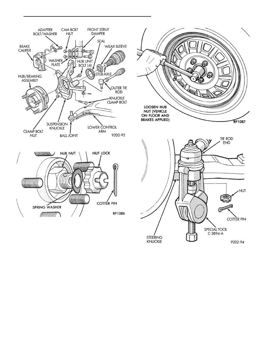
(6) Disconnect tie rod end from steering arm with
Puller Special, Tool C-3894-A (Fig. 5).
(7) Remove clamp bolt securing the ball joint stud
into the steering knuckle (Fig. 6).
(8) Remove caliper guide pin bolts (Fig. 6) and sepa-
rate caliper assembly from braking disc. Support
caliper with wire hook and not by hydraulic
hose. (Fig. 7) Remove braking disc from hub and
bearing assembly (Fig. 8).
(9) Separate the steering knuckle assembly from the
ball joint stud. Pull knuckle assembly out and away
from driveshaft (Fig. 9).
Care must be taken not to separate the inner
C/V joint during this operation. Do not allow
driveshaft to hang by inner C/V joint, driveshaft
must be supported.
(10) Remove the four hub and bearing assembly
mounting bolts from rear of steering knuckle (Fig. 9).
(11) Remove the hub and bearing assembly from
the steering knuckle (Fig. 10). Replacement of the
grease seal is recommended whenever this ser-
vice is performed.
INSTALLATION
CAUTION: All steering knuckle and bearing mounting
surfaces must be smooth and completely free of
foreign material or nicks.
(1) Install new front hub and bearing assembly into
the steering knuckle. Tighten the hub and bearing
assembly to steering knuckle attaching bolts (Fig. 9), in
a criss-cross pattern to 65 N
Im (45 ft. lbs.) torque.
Fig. 2 Front Hub And Bearing Assembly Mounting
Fig. 3 Remove Cotter Pin, Nut Lock, & Spring
Washer
Fig. 4 Loosen Hub Nut
Fig. 5 Disconnect Tie Rod End
Ä
SUSPENSION AND DRIVESHAFTS
2 - 21