Chrysler Le Baron, Dodge Dynasty, Plymouth Acclaim. Manual - part 80


  Index      Chrysler     Chrysler Le Baron, Dodge Dynasty, Plymouth Acclaim - service repair manual 1993 year


Search            


Content   ..  78  79  80  81   ..


Chrysler Le Baron, Dodge Dynasty, Plymouth Acclaim. Manual - part 80


Care must be taken not to separate the inner

C/V joint during this operation. Do not allow
driveshaft to hang by inner C/V joint, driveshaft
must be supported.

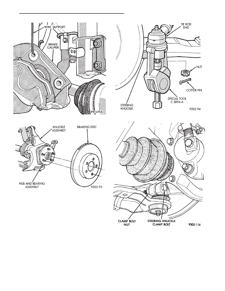
(10) Remove the steering knuckle to strut damper

attaching bolt and cam bolt (Fig. 9). Note the location
of the cam bolt, it must be installed in the same
location when steering knuckle is installed back
on strut damper.

(11) Mount the steering knuckle in a vise and re-

move the 4 bolts on back of steering knuckle, attaching
the hub and bearing assembly. Remove the hub and
bearing assembly from the steering knuckle (Fig. 10).

Remove outer C/V joint seal from the steering

knuckle.

INSTALL

CAUTION: Knuckle and bearing mounting surfaces
must be smooth and completely free of foreign ma-
terial or nicks.

Fig. 6 Disconnect Tie Rod End

Fig. 7 Remove or Install Steering Knuckle Clamp

Bolt

Fig. 4 Supporting Brake Caliper

Fig. 5 Remove or Install Braking Disc

Ä

SUSPENSION AND DRIVESHAFTS

2 - 17

(1) Install the hub and bearing assembly into the

steering knuckle (Fig. 10). Install the 4 hub and bearing
assembly to steering knuckle attaching bolts and torque
in a criss-cross pattern to 65 N

Im (45 ft.lbs.)

(2) Position new seal in recess on back of the steering

knuckle. Assemble Installer, Special Tool C-4698. Then
install seal into steering knuckle until it is fully seated
into recess (Fig. 11). Inspect the wear sleeve on the C/V
joint housing and replace if required.

(3) Install the steering knuckle back on the strut

damper (Fig. 9). Install the strut damper to steering
knuckle attaching bolt, cam bolt, washer plate and
nuts. Torque bolts to 100 N

Im (75 ft.lbs.) plus 1/4

turn.Be sure the cam bolt is installed in same
location it was removed from.

(4) Lubricate the FULL circumference of the seal

(and wear sleeve) with Mopar

t Multi-Purpose Lubri-

cant, or equivalent (Fig. 12).

(5) Slide the drive shaft back into the hub and

bearing assembly and install the steering knuckle
onto the ball joint stud (Fig. 13).

(6) Install the original (or equivalent) steering

knuckle to ball joint stud, clamp bolt and nut (Fig.
14). Torque the clamp bolt to 145 N

Im (105 ft. lbs.).

Fig. 10 Remove Or Install Hub and Bearing

Assembly

Fig. 11 Seal Installation In Steering Knuckle

Fig. 8 Separate Ball Joint Stud from Knuckle As-

sembly

Fig. 9 Remove Or Install Steering Knuckle

2 - 18

SUSPENSION AND DRIVESHAFTS

Ä

(7) Install the tie rod end into the arm of the steer-

ing knuckle. Install the tie rod end to steering
knuckle attaching nut, and torque to

47 N

Im (35 ft. lbs.). Install a new cotter pin into

the tie rod end (Fig. 15).

(8) Install the braking disk back on the hub and

bearing assembly (Fig. 5).

(9) Install the front brake caliper and adapter back

over the braking disc and align with the adapter
mounting holes on steering knuckle (Fig. 1). Install
the caliper adapter to steering knuckle attaching
bolts and torque to 217 N

Im (160 ft. lbs.).

(10) Clean all foreign matter from the threads of

the stub axle (Fig. 16). Install the washer and hub
nut onto the threads of the stub axle and tighten
nut.

(11) With the vehicles brakes applied to keep front

braking disc and hub from turning. Tighten the hub
nut to a torque of 244 N

Im (180 ft. lbs.) (Fig. 17).

(12) Install the spring washer, hub nut lock, and

new cotter pin. Wrap the cotter pin prongs tightly
around the hub nut lock (Fig. 18).

(13) Install the front wheel and tire assembly. In-

stall the front wheel lug nuts and torque to 129 N

Im

(95 ft.lbs.).

Fig. 13 Installing Knuckle Assembly

Fig. 12 Seal and Wear Sleeve Lubrication

Fig. 14 Tighten Steering Knuckle Clamp Bolt

Fig. 15 Install Tie Rod End

Ä

SUSPENSION AND DRIVESHAFTS

2 - 19

(14) Lower vehicle.
(15) Align the front wheels of the vehicle. Use the

procedure listed under Wheel Alignment, in the
Front Suspension Service Procedures section of this
service manual.

HUB AND BEARING ASSEMBLY

The Unit III Front Hub and Bearing (Fig. 1) is used

on all Front Wheel Drive Applications.

All hub and bearing assemblies mount to the steer-

ing knuckle the same way, but very by the wheel size
on the vehicle. Vehicles equipped with 14 inch wheels
have a 4 inch wheel mounting stud pattern. Vehicles
equipped with 15 inch wheels have a 4 1/2 inch wheel
mounting stud pattern. If a hub and bearing assembly
needs to be replaced, be sure that the replacement
assembly has the same size wheel mounting stud
pattern as the original part.

This unit is serviced only as a complete assembly

(Fig. 1). It is mounted to the steering knuckle by four
mounting bolts that are removed from the rear of the
steering knuckle (Fig. 2).

REMOVAL

Replacement of the front (drive) hub and bearing

assembly can be done without having to remove the
steering knuckle from the vehicle.

(1) Remove cotter pin, hub nut lock, and spring

washer (Fig. 3).

(2) Loosen hub nut while the vehicle is on the floor

with the brakes applied (Fig. 4). The hub and drive-
shaft are splined together through the knuckle
(bearing assembly) and retained by the hub nut.

(3) Raise vehicle, see Hoisting Recommendations in

Group 0 of this service manual.

(4) Remove the hub nut and the washer from the

stub axle (Fig. 3).

(5) Remove the wheel lug nuts, and tire and wheel

assembly from the vehicle.

Fig. 16 Install Washer and Hub Nut

Fig. 17 Tighten Hub Nut

Fig. 18 Install Spring Washer, Nut Lock, & Cotter

Pin

Fig. 1 Unit III Front Hub And Bearing Assembly

2 - 20

SUSPENSION AND DRIVESHAFTS

Ä


Content   ..  78  79  80  81   ..