Chrysler Le Baron, Dodge Dynasty, Plymouth Acclaim. Manual - part 78


  Index      Chrysler     Chrysler Le Baron, Dodge Dynasty, Plymouth Acclaim - service repair manual 1993 year


Search            


Content   ..  76  77  78  79   ..


Chrysler Le Baron, Dodge Dynasty, Plymouth Acclaim. Manual - part 78


(a) Severe deterioration of rubber isolator; re-

tainers for cracks and distortion and bond failure of
retainers and rubber isolators.

(b) Bearings for binding.
(c) Shock Absorber for flat spots over full stroke

also see, Shock Absorbers, (strut damper).

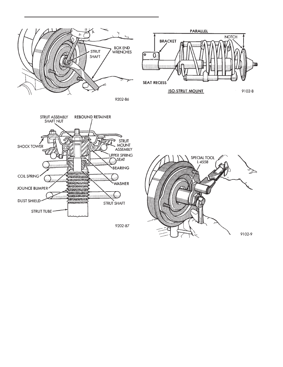
ASSEMBLE (STRUT DAMPER)

(1) Mount the strut assembly in a vertical position.
(2) Place the compressed spring onto the strut as-

sembly, so the end of the coil is seated in the seat re-
cess in lower spring mount (Fig. 9).

(3) Install the dust shield, isolator (if so equipped)

jounce bumper, spacer (as required), and spring seat
onto the top of the strut shaft (Fig. 8).

(4) Position top spring seat alignment tab correctly

with respect to bottom bracket (Fig. 9).

(5) Install the rebound retainer and shaft nut (Fig.

8).

(6) Tighten the strut shaft nut using, Strut Rod

Socket And Holder, Special Tool L-4558. Torque strut
shaft nut to 75 N

Im (55 ft. lbs.) plus 1/4 turn (Fig. 10).

WARNING: THIS STEP MUST BE DONE BEFORE
SPRING COMPRESSOR, SPECIAL TOOL C-4838 IS
RELEASED FROM THE COIL SPRING.

(7) Verify coil spring is aligned correctly with respect

to bottom bracket (Fig. 9).

(8) Release Spring Compressor Tool C-4838.

SUSPENSION COIL SPRINGS

Springs are rated separately for each side of vehicle

depending on optional equipment and type of service.
During service procedures where both springs are
removed, mark springs (Chalk, Tape, etc.) (Fig. 11) to
ensure installation in original position. If the coils
springs require replacement. Be sure that the
springs needing replacement, are replaced with
springs meeting the correct load rating for the
vehicle and its specific options.

During service procedures requiring the re-

moval or installation of a coil spring with Spring

Fig. 7 Loosening Strut Assembly Shaft Nut

Fig. 8 Mount Assembly

Fig. 9 Spring Seat Alignment Notch Position to

Bracket

Fig. 10 Tighten Strut Rod Nut with Tool

Ä

SUSPENSION AND DRIVESHAFTS

2 - 9

Compressor, Special Tool C-4838. It is required
that five coils be captured within the jaws of the
tool (Fig. 11).

SPRING RETAINER UPPER

Ensure that upper spring retainer is positioned

properly, see; step (4), Assemble (Strut Damper).

SPRING SEAT LOWER

During assembly of the coil spring to strut damper.

Ensure that lower coil spring end is seated in strut
damper spring seat recess refer to (Fig. 9) in assem-
ble (Strut Damper) section.

SHOCK ABSORBERS (Strut Damper)

INSPECTION

Inspect for evidence of fluid leaking from around

the strut assembly shaft seal at the upper end of the
reservoir. (Actual leakage will be a stream of fluid
running down the side and dripping off lower end of
unit. A slight amount of seepage around the strut
rod is not unusual and does not affect performance.

LOWER CONTROL ARM

The lower control arm if damaged, is serviced only

as a complete component. Do not attempt to repair or
straighten a broken or bent lower control arm.

The serviceable components of the lower control

arm are, the ball joint assembly, and both pivot
bushings. The service procedure to replace these com-
ponents is detailed in the specific component sections
of this group.

REMOVAL (ASSEMBLY)

(1) Raise vehicle. See Hoisting in Lubrication,

Group 0 of this service manual.

(2) Remove the ball joint stud to steering knuckle

clamp nut and bolt (Fig. 1).

(3) Remove the sway bar to lower control arm re-

tainer on both sides of the vehicle (Fig. 2). Then ro-
tate the sway bar down away from the lower control
arms.

(4) Separate the steering knuckle from the ball

joint stud (Fig. 1).

(5) Remove the front and rear control arm pivot

bushing to crossmember attaching nuts and bolts
(Fig. 2). Then remove the lower control arm from the
crossmember.

CAUTION: Pulling steering knuckle out from vehicle
after releasing from ball joint can separate inner
C/V joint. See Driveshafts.

Fig. 11 Identifying Coil Springs

Fig. 1 Control Arm To Steering Knuckle Attachment

Fig. 2 Lower Control Arm Typical

2 - 10

SUSPENSION AND DRIVESHAFTS

Ä

Inspect lower control arm for distortion. Check

bushings for severe deterioration.

INSTALLATION (ASSEMBLY)

(1) Position the lower control arm into the cross-

member. Install front and rear pivot bushing to
crossmember attaching bolts. Then loosely assemble
nuts to bolts (Fig. 2).

(2) Install ball joint stud into steering knuckle and

install clamp bolt (Fig. 1). Tighten clamp bolt to 145
N

Im (105 ft. lbs.).

(3) Position sway bar and bushings against the

lower control arms. Install sway bar to control arm
retainers. Install retainer bolts and tighten to 70
N

Im (50 ft. lbs.).

(4) Lower vehicle so the suspension is supporting

vehicles weight (control arm at design height).
Tighten the lower control arm to crossmember at-
taching bolts to 169 N

Im (125 ft. lbs.) torque.

LOWER CONTROL ARM PIVOT BUSHINGS

When performing the replacement procedure on the

lower control arm pivot bushings, the following se-
quence must be followed. When removing the pivot
bushings from the lower control arm, the large bush-
ing must be removed first then the small bushing.
When installing the pivot bushings into the lower
control arm, the small bushing must be installed
first then the large bushing. This sequence must be
used when removal and replacement of bushings is
done using Bushing Remover/Installer, Special Tool
6602.

LARGE BUSHING

REMOVE

(1) Position and clamp lower control arm in a vise.
(2) Assemble the washer, thrust bearing and large

bushing disk, Special tool 6602-5 onto the threaded
rod from Bushing Remover/Installer, Special Tool
6602 (Fig. 3).

(3) Install the tools assembled in step 2 above into

the large bushing of the lower control arm (Fig. 4).
Then assemble the remaining Special Tools, Cup
6602-2, thrust bearing, washer and long nut onto the
threaded rod (Fig. 4) from Bushing Remover/In-
staller, Special Tool 6602.

(4) Hold the long nut stationary. Using a deep

socket turn the long threaded rod until the large
pivot bushing is pushed out of the lower control arm.

SMALL BUSHING

REMOVE

(1) Remove the special tools from the lower control

arm that were used for the removal of the large pivot
bushing.

(2) Remove the large Bushing Disc, Special Tool

6602-5 from the threaded rod. Leave the thrust bear-
ing and washer on the threaded rod. Install the small
Bushing Disc, Special Tool 6602-3 on the threaded
rod and against thrust bearing (Fig. 5).

Fig. 3 Bushing Removal Tools

Fig. 4 Tool Assembled For Bushing Removal

Fig. 5 Bushing Removal Tools

Ä

SUSPENSION AND DRIVESHAFTS

2 - 11

(3) Install the tools assembled in step 2 above

through small lower control arm bushing and hole in
lower control arm where large bushing was removed
from (Fig. 6). Assemble the Cup, Special Tool 6602-2
thrust bearing, washer and long nut onto the
threaded rod of Special Tool 6602 (Fig. 6). Cup, Spe-
cial Tool 6602-2 is to be installed on threaded rod
with cup facing out and undercut in large bushing
hole of lower control arm (Fig. 6).

(4) Hold the threaded rod stationary and turn the

long nut until the small pivot bushing is pulled out
of the lower control arm.

SMALL BUSHING

INSTALL

(1) Remove the special tools from the lower control

arm that were used for the removal of the small
pivot bushing.

(2) On the threaded rod from Remover/Installer,

Special Tool 6602 assemble the following pieces.
Washer, thrust bearing, small bushing disc Special
Tool 6602-3, small lower control arm pivot bushing
and small bushing sizer, Special Tool 6602 (Fig. 7).

(3) Install the pieces assembled in step 2 through

the small and large pivot bushing holes in the lower
control arm. At the large pivot bushing hole in the
lower control arm, assemble Cup, Special Tool
6602-2, thrust bearing, washer and nut (Fig. 8). Cup,
Special Tool 6602-2 is to be installed on threaded rod
with cup facing out and undercut in large bushing
hole of lower control arm (Fig. 8). Lubricate the in-
staller cone and new bushing using Mopar

t, Silicone

Spray Lube or equivalent.

(4) Hold the threaded rod stationary and turn the

long nut until the small pivot bushing is fully in-
stalled into the lower control arm. Be sure that the
flanges of the bushing are fully expanded around the
control arm bushing holes.

LARGE BUSHING

INSTALL

(1) Remove the special tools from the lower control

arm that were used for installing the small pivot
bushing.

(2) On the threaded rod from Remover/Installer,

Special Tool 6602 assemble the following pieces.
Washer, thrust bearing, Cup Special Tool 6602-2
(Fig. 9).

(3) Install the pieces assembled in step 2 through

the hole in the small pivot bushing and the large
pivot bushing hole in the lower control arm. At the
large pivot bushing hole in the lower control arm as-
semble the following special tool pieces. Large Bush-
ing Sizer, Special Tool 6602-4, large lower control
arm pivot bushing, large bushing disc Special Tool
6602-5, thrust bearing, washer and nut (Fig. 10). Lu-
bricate the installer cone and new bushing using Mo-
par

t Silicone Spray Lube or equivalent.

(4) Hold the threaded rod stationary and turn the

long nut until the bushing is fully installed into the

Fig. 6 Tool Assembled For Bushing Removal

Fig. 7 Bushing Installing Tools Assembled

Fig. 8 Bushing And Tool Position For Installation In

Control Arm

2 - 12

SUSPENSION AND DRIVESHAFTS

Ä


Content   ..  76  77  78  79   ..