Chrysler Le Baron, Dodge Dynasty, Plymouth Acclaim. Manual - part 76


  Index      Chrysler     Chrysler Le Baron, Dodge Dynasty, Plymouth Acclaim - service repair manual 1993 year


Search            


Content   ..  74  75  76  77   ..


Chrysler Le Baron, Dodge Dynasty, Plymouth Acclaim. Manual - part 76


SUSPENSION AND DRIVESHAFTS

CONTENTS

page

page

AUTOMATIC AIR LOAD LEVELING SYSTEM

59

AUTOMATIC AIR SUSPENSION

. . . . . . . . . . . . 73

DRIVESHAFTS

. . . . . . . . . . . . . . . . . . . . . . . . . 25

FRONT SUSPENSION

. . . . . . . . . . . . . . . . . . . . . 2

FRONT SUSPENSION SERVICE PROCEDURES . 5

GENERAL INFORMATION . . . . . . . . . . . . . . . . . . 1
REAR (STUB) AXLE ALIGNMENT ALL

MODELS

. . . . . . . . . . . . . . . . . . . . . . . . . . . . 89

REAR SUSPENSION

. . . . . . . . . . . . . . . . . . . . . 50

SPECIFICATIONS

. . . . . . . . . . . . . . . . . . . . . . . 91

GENERAL INFORMATION

Throughout this group, references may be made to

a particular vehicle by letter or number designation.
A chart showing the breakdown of these designations
is included in the Introduction section at the front of
this Service Manual.

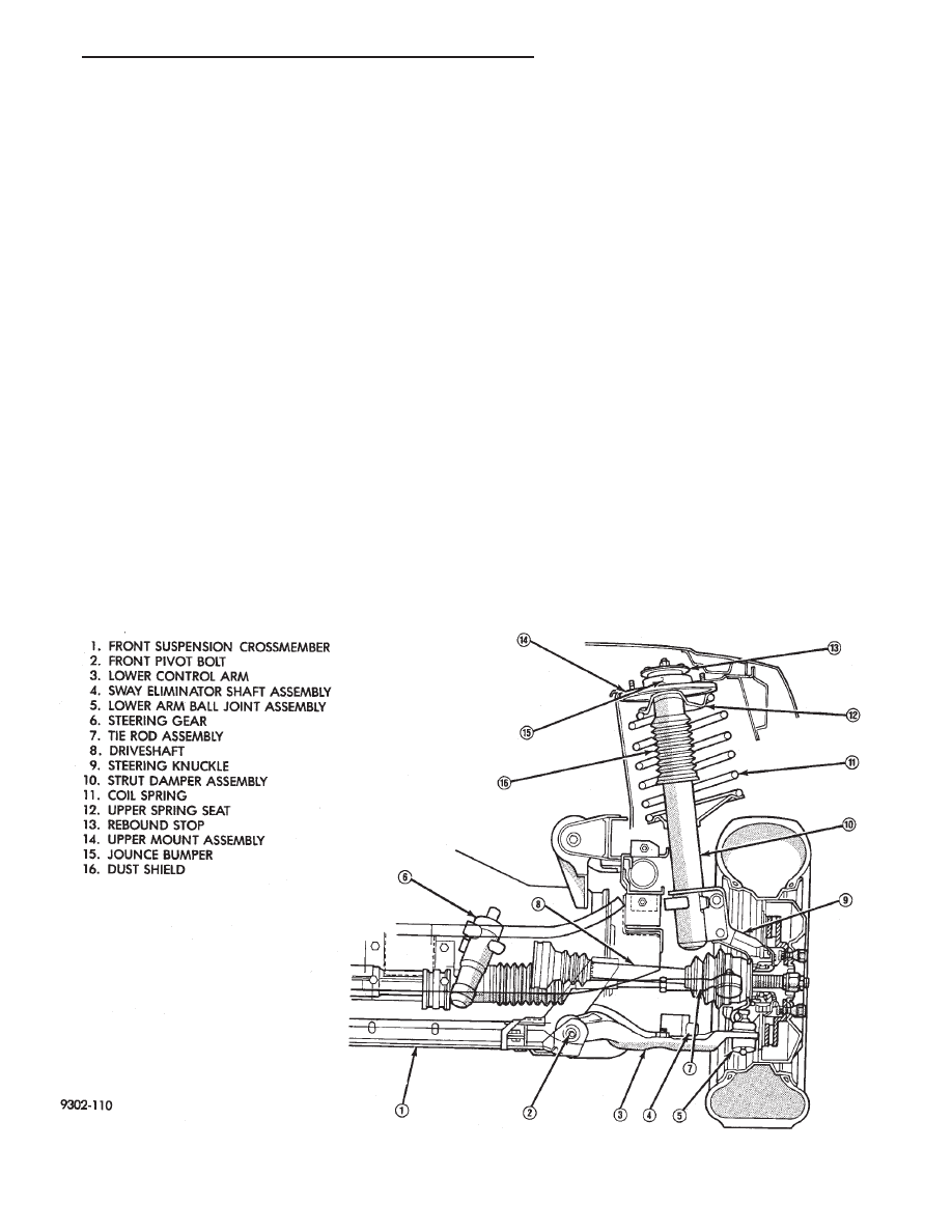
An independent MacPherson Type front suspension

is used on these vehicles. Vertical shock absorbing
struts attach to the upper fender reinforcement and

the steering knuckle to provide upper steering
knuckle position. Lower control arms are attached
inboard to a crossmember and outboard to the steer-
ing knuckle through a ball joint to provide lower
steering knuckle position. During steering maneu-
vers, the strut (through a pivot bearing in the upper
retainer) and the steering knuckle turn as an assem-
bly (Fig. 1).

Fig. 1 Front Suspension (Typical)

Ä

SUSPENSION AND DRIVESHAFTS

2 - 1

FRONT SUSPENSION

FRONT SUSPENSION MAJOR COMPONENTS
(FIG. 2)

STRUT SUPPORT

The system is supported by coil springs positioned

offset around the struts. The springs are contained
between an upper seat, located just below the top
strut mount assembly (Fig. 2) and a lower spring
seat on the strut lower housing.

The top of each strut assembly is bolted to the up-

per fender reinforcement (shock tower) through a
rubber isolated mount.

The bottom attaches to the top of the steering

knuckle with two through bolts. On some vehicles,
one bolt has an eccentric cam located below the head
of the bolt for camber adjustment. On the other ve-
hicles the camber adjustment is done by manually
moving the steering knuckle within the strut assem-
bly. Caster is a fixed setting on all vehicles and is
not adjustable.

STEERING KNUCKLE

The steering knuckle is a single casting with legs

machined for attachment to the strut damper, steer-
ing linkage, brake adaptor, and lower control arm
ball joint. The knuckle also holds the front drive hub
bearing. The hub is positioned through the bearing
and knuckle, with the constant velocity stub shaft
splined through the hub.

LOWER CONTROL ARM

The lower control arm is a steel casting with 2

large spool type rubber pivot bushings. The lower
control arm is bolted to the crossmember with pivot
bolts through the center of the rubber pivot bush-
ings.

The ball joint is pressed into the control arm and

has a non-tapered stud with a notch for clamp bolt
clearance. The stud is clamped and locked into the
steering knuckle leg with a clamp bolt.

The lower control arms are inter-connected through

a rubber isolated sway bar (Fig. 2).

DRIVESHAFTS

A left and right driveshaft is attached inboard to

the transaxle differential side gears, and outboard to
the driven wheel hub.

To deliver driving force from the transaxle to the

front wheels during turning maneuvers and suspen-
sion movement. Both shafts are constructed with con-
stant velocity universal joints at both ends.

Both shafts have a Tripod (sliding) joint at the

transaxle end and Rzeppa joints (with splined stub
shafts) on the hub ends. Due to the transaxle loca-
tion the connecting shafts between the C/V joints are
of different length and construction. The right shaft
is longer and of tubular construction. The left shaft
is solid.

2 - 2

SUSPENSION AND DRIVESHAFTS

Ä

Fig.

2

Front

Suspension

Components

Ä

SUSPENSION AND DRIVESHAFTS

2 - 3

SUSPENSION/STEERING/DIAGNOSIS FRONT WHEEL DRIVE

2 - 4

SUSPENSION AND DRIVESHAFTS

Ä


Content   ..  74  75  76  77   ..