Chrysler Le Baron, Dodge Dynasty, Plymouth Acclaim. Manual - part 75


  Index      Chrysler     Chrysler Le Baron, Dodge Dynasty, Plymouth Acclaim - service repair manual 1993 year


Search            


Content   ..  73  74  75  76   ..


Chrysler Le Baron, Dodge Dynasty, Plymouth Acclaim. Manual - part 75


(9) Loosen but do not remove the interlock lever

adjusting nut (Fig. 10) on the shifter assembly.

(10) Remove interlock cable slug, from interlock le-

ver on shifter assembly (Fig. 10). Remove interlock
cable from shifter assembly by grasping cable and
pulling straight out from front of shifter assembly
(Fig. 11).

(11) Remove the interlock cable routing clip from

the throttle pedal bracket (Fig. 12). Removal of the
clip can be done by using needle nose pliers to com-
press barbs on clip and removing from holes in
bracket.

(12) Remove the 2 screws holding the interlock

mechanism to the steering column (Fig. 13). Mecha-
nism is held to column by clips on back of mecha-
nism,

then

pull

mechanism

straight

out

from

steering column.

(13) Remove interlock cable from routing clip on

lower steering column mounting bracket.

(14) Route interlock cable from under center con-

sole mounting bracket and out front of dash panel.

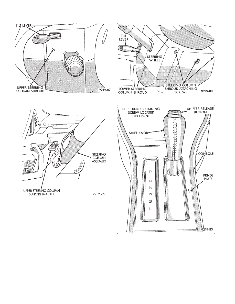
Fig. 6 Upper Steering Column Shroud And Tilt

Lever

Fig. 7 Steering Column Mounting Bracket

Fig. 8 Lower Steering Column Shroud

Fig. 9 Shift Knob And PRNDL Plate Removal

Ä

STEERING

19 - 39

INSTALL

CAUTION: When installing interlock cable assem-
bly, care must be taken not to bend exposed cable
wire and slug at shifter end of cable.

(1) Route interlock cable into lower dash panel and

down under the center console mounting bracket
(Fig. 1). Cable must be routed above the lower dash
panel support bracket and above throttle pedal base.

(2) Turn the ignition switch to the RUN position

(Fig. 1). Install the interlock mechanism on the
steering column, by locking tabs on back of mecha-
nism into large square opening on steering column.

(3) Move cam on interlock mechanism by hand, al-

lowing slider to move into cam and ignition switch to
rotate to the ACCESSORY position. Then turn the
ignition switch to the ACCESSORY position (Fig. 1).

(4) Install the 2 interlock mechanism to steering

column attaching screws (Fig. 13) and torque to 3
N

Im (21 in. lbs.).

(5) Install interlock cable into routing clip on

lower steering column mounting bracket.

Fig. 10 Interlock Adjusting Nut

Fig. 11 Interlock Cable Removal

Fig. 12 Remove Interlock Routing Clip

Fig. 13 Removing Interlock Mechanism

19 - 40

STEERING

Ä

CAUTION:

Interlock

cable

must

by

completely

clipped to the throttle pedal bracket with both barbs
of clip fully installed through mounting holes. This
is to prevent interference with throttle pedal.

(6) Snap the interlock cable routing clip into the 2

holes on the throttle pedal mounting bracket (Fig.
12).

(7) Snap the end fitting of the interlock cable into

the corner of the shifter assembly (Fig. 14). The cable
end and clip must pass under and clip to the shifter
pivot.

(8) Install slug on end of interlock cable into notch,

on shifter lockout spring loaded lever (Fig. 15). Make
sure that cable slug is fully seated in cup of lever as-
sembly.

(9) Adjust the Shifter/Ignition Interlock System.

See Interlock System Adjustment, in this section of
service manual.

(10) Perform the Shifter/Ignition Interlock System

operation check, as described in the beginning of this
section.

(11) Install

center

console

assembly.

Refer

to

Group 23 Body, in this service manual for the appro-
priate procedure for the body style

being serviced.
(12) Install PRNDL plate in center console. Install

the shift knob onto the shifter assembly. Install the
shift knob to shifter retaining screw and torque to 3
N

Im (25 in.lbs.) (Fig. 2).

(13) Install the lower steering column shrouds on

the steering column (Fig. 8). Tighten the 2 lower
shroud to steering column screws.

(14) Make sure ground clip is on left breakaway

capsule. Make sure that both breakaway capsules are
fully seated in the upper steering column bracket. In-
stall the upper steering column mounting bracket
onto the steering column support bracket (Fig. 7). In-
stall the 2 upper steering column bracket to support
bracket nuts and torque to 12 N

Im (105 in. lbs.).

(15) Install the upper steering column shrouds on

the steering column (Fig. 6). Tighten the 3 upper
shroud to steering column attaching screws.

(16) Install the tilt lever (Fig. 6) (if so equipped)

back on the steering column assembly.

(17) Install the lower dash panel bolster. Install

bolster attaching screws and torque to 3 N

Im (24 in.

lbs.). Install the inside hood release lever and torque
screws to 3 N

Im (24 in. lbs.) (Fig. 5).

(18) Reconnect the battery negative (-) cable to the

vehicle battery.

Fig. 14 Interlock Cable Installation

Fig. 15 Install Interlock Cable In Shifter

Ä

STEERING

19 - 41

SPECIFICATIONS AND TIGHTENING REFERENCE

POWER STEERING PUMP SPECIFICATIONS

TORQUE SPECIFICATIONS

19 - 42

STEERING

Ä


Content   ..  73  74  75  76   ..