Index Chrysler Chrysler Le Baron, Dodge Dynasty, Plymouth Acclaim - service repair manual 1993 year
Search
Content .. 53 54 55 56 ..
Chrysler Le Baron, Dodge Dynasty, Plymouth Acclaim. Manual - part 55
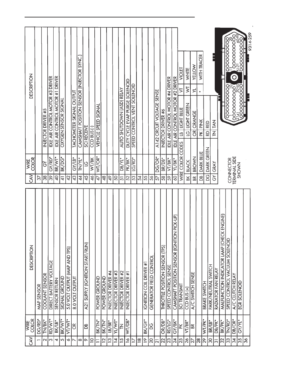
Fig.
7
60-W
ay
PCM
W
iring
Connector—3.0L
Engine
Ä
FUEL SYSTEMS
14 - 137