Chrysler Le Baron, Dodge Dynasty, Plymouth Acclaim. Manual - part 37


  Index      Chrysler     Chrysler Le Baron, Dodge Dynasty, Plymouth Acclaim - service repair manual 1993 year


Search            


Content   ..  35  36  37  38   ..


Chrysler Le Baron, Dodge Dynasty, Plymouth Acclaim. Manual - part 37


The exhaust gas oxygen content input is not ac-

cepted by the PCM during wide open throttle opera-
tion. The PCM will enrichen the air/fuel ratio to
increase performance and compensate for increased
combustion chamber temperature.

The PCM determines the methanol content of the

fuel from the methanol concentration sensor input.

IGNITION SWITCH OFF MODE

This is an OPEN LOOP mode. When the ignition

switch is turned to the OFF position, the following
occurs:
• All outputs are turned off.

• No inputs are monitored.
• The PCM shuts down.

THROTTLE BODY

The throttle body houses the throttle position sen-

sor (TPS) and the idle air control motor (Fig. 15). Air
flow through the throttle body is controlled by a ca-
ble operated throttle blade at the base of the throttle
body.

FUEL SUPPLY CIRCUIT

Fuel is pumped to the fuel rail by an electrical

pump in the fuel tank. A filter, attached to the pump
inlet, prevents water and other contaminants from
entering the fuel supply circuit.

The vacuum assisted fuel pressure regulator keeps

fuel pressure at 380 kPa (55 psi). The regulator uses
intake manifold pressure at the vacuum tee as a ref-
erence.

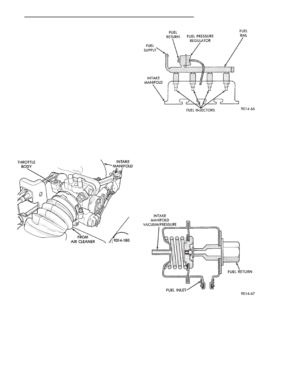
FUEL INJECTORS AND FUEL RAIL ASSEMBLY

Four fuel injectors are retained in the fuel rail by

lock rings (Fig. 16). The fuel injectors and rail bolt in
position with the injectors inserted into recessed
holes in the intake manifold.

FUEL PRESSURE REGULATOR

The pressure regulator is located downstream of

the fuel injector on the fuel rail (Fig. 17). The regu-
lator maintains constant 380 kPa (55 PSI) fuel pres-
sure across the fuel injector tip.

The regulator has a spring loaded rubber dia-

phragm that uncovers a fuel return port. When the
fuel pump operates, fuel flows past the injector into
the regulator. Fuel is restricted from flowing any fur-
ther by the blocked return port. When fuel pressure
reaches 380 kPa (55 PSI), it pushes on the dia-
phragm, compresses the spring, and uncovers the
fuel return port. The diaphragm and spring continu-
ally move from an open to closed position keeping
the fuel pressure consistent.

Fig. 15 Throttle Body

Fig. 16 Fuel Supply System

Fig. 17 Fuel Pressure Regulator

Ä

FUEL SYSTEMS

14 - 65

2.5L FLEXIBLE FUEL MULTI-PORT FUEL INJECTION—GENERAL DIAGNOSIS

INDEX

page

page

Fuel System Diagram

. . . . . . . . . . . . . . . . . . . . . 66

Visual Inspection

. . . . . . . . . . . . . . . . . . . . . . . . . 66

FUEL SYSTEM DIAGRAM

Refer to the Component Identification portion of

this section for a more complete description of the
components shown in Figure 1.

VISUAL INSPECTION

Perform a visual inspection for loose, disconnected,

or misrouted wires and hoses before diagnosing or
servicing the fuel injection system. A visual check
helps save unnecessary test and diagnostic time. A
thorough visual inspection includes the following
checks:

(1) Check Ignition Coil Electrical Connections (Fig.

2).

(2) Verify the electrical connector is attached to

the Canister Purge Solenoid (Fig. 3). Check the vac-
uum connections at the solenoid and canister.

(3) Verify the electrical connector is attached to

the MAP sensor (Fig. 4). Inspect the MAP sensor
vacuum hose for damage and leaks.

(4) Verify generator wiring and belt are correctly

installed and tightened.

Fig. 1 Flexible Fuel MPI Components

Fig. 2 Ignition Coil Electrical Connection

14 - 66

FUEL SYSTEMS

Ä

(5) Check Ignition Cable Routing and Attachment

(Fig. 5).

(6) Check both electrical connectors at the distrib-

utor.

(7) Check radiator fan electrical connector.
(8) Check the engine coolant temperature sensor

electrical connection. Inspect battery ground cable
connection (Fig. 6).

(9) Inspect the engine temperature sensor electri-

cal connection (Fig. 7).

(10) Check power brake booster and speed control

vacuum connections (Fig. 8).

(11) Check engine harness to main harness electri-

cal connections.

(12) Check park/neutral switch wiring connection

(Fig. 9).

(13) Ensure battery connections are clean and

tight.

(14) Inspect relay connections (Fig. 10)
(15) Ensure the 60-way connector is fully inserted

into the socket on the PCM (Fig. 11). Make sure the
wires are not stretched or pulled out of the connector.

Fig. 3 EVAP Purge Solenoid

Fig. 4 MAP Sensor

Fig. 5 Ignition Cable Mounting and Attachment

Fig. 6 Engine Coolant Temperature Sensor

Fig. 7 Engine Temperature Sensor Electrical

Connection

Ä

FUEL SYSTEMS

14 - 67

(16) Verify the harness connector is attached to

idle air control motor (Fig. 12).

(17) Verify the harness connector is attached to

the throttle position sensor (Fig. 12).

Fig. 8 Power Brake Booster and Speed Control

Vacuum Hose Connections

Fig. 9 Automatic Transaxle Electrical Connections

Fig. 10 Relay Identification

Fig. 11 PCM Electrical Connector

Fig. 12 TPS and Idle Air Control Motor

14 - 68

FUEL SYSTEMS

Ä


Content   ..  35  36  37  38   ..