Chrysler Le Baron, Dodge Dynasty, Plymouth Acclaim. Manual - part 35


  Index      Chrysler     Chrysler Le Baron, Dodge Dynasty, Plymouth Acclaim - service repair manual 1993 year


Search            


Content   ..  33  34  35  36   ..


Chrysler Le Baron, Dodge Dynasty, Plymouth Acclaim. Manual - part 35


The second method of reading diagnostic trouble

codes uses the DRBII scan tool. For diagnostic trou-
ble code information, refer to the On-Board Diagnos-
tics section in this group.

CCD BUS

Various modules exchange information through a

communications port called the CCD Bus. The pow-
ertrain control module transmits vehicle load data on
the CCD Bus.

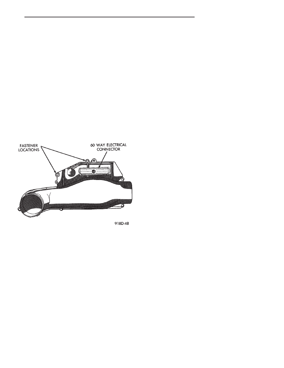
POWERTRAIN CONTROL MODULE

The powertrain control module (PCM) is a digital

computer containing a microprocessor (Fig. 2). The
PCM receives input signals from various switches
and sensors referred to as Powertrain Control Mod-
ule Inputs. Based on these inputs, the PCM adjusts
various engine and vehicle operations through de-
vices referred to as Powertrain Control Module Out-
puts.

PCM Inputs:

• Air Conditioning Controls

• Battery Voltage

• Brake Switch

• Engine Coolant Temperature Sensor

• Camshaft Position Sensor (Distributor Pick-up)

• Manifold Absolute Pressure (MAP) Sensor

• Methanol Concentration Sensor

• Oxygen Sensor

• SCI Receive

• Speed Control System Controls

• Throttle Position Sensor

• Park/Neutral Switch (automatic transaxle)

• Vehicle Speed Sensor

PCM Outputs:

• Air Conditioning Clutch Relay

• Generator Field

• Auto Shutdown (ASD) Relay

• Duty Cycle EVAP Canister Purge Solenoid

• Data Link (Diagnostic) Connector

• Fuel Injectors

• Idle Air Control Motor

• Ignition Coil

• Malfunction Indicator (Check Engine) Lamp

• Radiator Fan Relay

• Speed Control Solenoids

• Tachometer Output

• Torque Converter Clutch Solenoid

Based on inputs it receives, the PCM adjusts fuel

injector pulse width, idle speed, ignition spark ad-
vance, ignition coil dwell and canister purge opera-
tion. The PCM regulates operation of the radiator
fan, A/C and speed control systems. Also, the PCM
changes generator charge rate by adjusting the gen-
erator field.

The PCM adjusts injector pulse width (air-fuel ra-

tio) based on the following inputs.
• Battery voltage

• Coolant temperature

• Exhaust gas content

• Engine speed

• Manifold absolute pressure

• Methanol percentage of fuel

• Throttle position

The PCM adjusts ignition timing based on the fol-

lowing inputs.
• Coolant temperature

• Engine speed

• Manifold absolute pressure

• Methanol percentage of fuel

• Throttle position

The auto shutdown (ASD) and fuel pump relays are

mounted externally. The PCM turns both relays on
and off through the same circuit.

The camshaft position sensor (distributor pick-up)

sends a signal to the PCM. If the PCM does not re-
ceive a camshaft position sensor signal within ap-
proximately

one

second

of

engine

cranking,

it

deactivates the ASD and fuel pump relays. When
these relays deactivate, they shut off power to the
fuel injectors, fuel pump, ignition coil, methanol con-
centration sensor and oxygen sensor heater element.

The

PCM

contains

a

voltage

converter

that

changes battery voltage to a regulated 8.0 volts to
power the distributor pick-up methanol concentration
sensor and vehicle speed sensor. The PCM also pro-
vides a 5.0 volts supply for the engine coolant tem-
perature sensor, manifold absolute pressure sensor
and throttle position sensor.

AIR CONDITIONING SWITCH SENSE—PCM INPUT

When the operator puts the A/C or defrost switch

in the ON position and the low pressure and high
pressure switches close, the PCM receives an input.
The input indicates the operator selected air condi-
tioning. After receiving this input, the PCM acti-
vates the A/C compressor clutch by grounding the

Fig. 2 Powertrain Control Module

Ä

FUEL SYSTEMS

14 - 57

A/C clutch relay. To compensate for increased engine
load, the PCM also adjusts idle speed to a scheduled
RPM.

BATTERY VOLTAGE—PCM INPUT

The powertrain control module (PCM) monitors the

battery voltage input to determine fuel injector pulse
width and generator field control. If battery voltage
is low, the PCM increases injector pulse width to
compensate.

BRAKE SWITCH—PCM INPUT

When the brake switch activates, the powertrain

control module (PCM) receives an input indicating
that the brakes are being applied. After receiving the
input, the PCM vents the speed control servo. Vent-
ing the servo turns the speed control system off.

ENGINE COOLANT TEMPERATURE SENSOR—PCM
INPUT

The coolant temperature sensor is installed behind

the thermostat housing and ignition coil in the ther-
mostat housing (hot box). The PCM supplies 5 volts
to the coolant temperature sensor. The sensor pro-
vides an input voltage to the PCM (Fig. 3). As cool-
ant temperature varies, the coolant temperature
sensor resistance changes resulting in a different in-
put voltage to the PCM.

The PCM demands slightly richer air-fuel mixtures

and higher idle speeds until the engine reaches nor-
mal operating temperature.

This sensor is also used for cooling fan control.

CAMSHAFT POSITION SENSOR—PCM INPUT

The camshaft position sensor (distributor pick-up)

supplies engine speed and the injector sync signal to
the powertrain control module (PCM). The sensor is
a Hall Effect device (Fig. 4).

A shutter (sometimes referred to as an interrupter)

is attached to the distributor shaft. The shutter con-
tains four blades, one per engine cylinder. A switch

plate is mounted to the distributor housing above the
shutter. The switch plate contains the camshaft posi-
tion sensor (distributor pick-up) through which the
shutter blades rotate. As the shutter blades pass
through the pick-up, they interrupt the magnetic
field. The Hall effect device in the pick-up senses the
change in the magnetic field and switches on and off
(which creates pulses), generating the input signal to
the PCM. The PCM calculates engine speed through
the number of pulses generated.

One of the shutter blades has a window cut into it.

The window tells the PCM which injector to energize.

MANIFOLD ABSOLUTE PRESSURE (MAP)
SENSOR—PCM INPUT

The powertrain control module (PCM) supplies 5

volts to the MAP sensor. The MAP sensor converts
intake manifold pressure into voltage. The PCM
monitors the MAP sensor output voltage. As vacuum
increases, MAP sensor voltage decreases proportion-
ately. Also, as vacuum decreases, MAP sensor volt-
age increases proportionately.

During cranking, before the engine starts running,

the PCM determines atmospheric air pressure from
the MAP sensor voltage. While the engine operates,
the PCM determines intake manifold pressure from
the MAP sensor voltage. Based on MAP sensor volt-
age and inputs from other sensors, the PCM adjusts
spark advance and the air/fuel mixture.

The MAP sensor mounts on the dash panel inside

the engine compartment (Fig. 5). A vacuum hose con-
nects the sensor to the throttle body.

Fig. 3 Coolant Temperature Sensor

Fig. 4 Camshaft Position Sensor (Distributor

Pick-Up)

14 - 58

FUEL SYSTEMS

Ä

METHANOL CONCENTRATION SENSOR—PCM
INPUT

The methanol concentration sensor contains a mi-

croprocessor that determines the percentage of gaso-
line and methanol in the fuel system. From the
methanol concentration sensor input, the powertrain
control module (PCM) determines the amount of
methanol in the fuel. The vehicle can operate on a
mixtures up to 85 percent methanol, 15 percent gas-
oline.

The PCM supplies 8 volts to the methanol concen-

tration sensor. The methanol concentration sensor
output voltages varies with the percent of methanol
in the fuel system. The sensor output voltage (input
for PCM) ranges from 0.5 volts for pure gasoline to
4.50 volts for 85 percent methanol. For two seconds
at key ON when the operator starts the vehicle, the
sensor calibrates the PCM. During the calibration
period the sensor sends 4.45 volts to the PCM as a
correction factor.

The methanol concentration sensor has a built-in

shutdown capability. If the sensor shuts down, the
PCM defaults to the previous learned value (output
voltage based on methanol percentage of fuel).

The methanol concentration sensor attaches to a

bracket at the rear of the fuel tank, next to the fuel
filler tube (Fig. 6).

HEATED OXYGEN SENSOR (O

2

SENSOR)—PCM

INPUT

The heated oxygen sensor is located in the exhaust

manifold. The sensor provides an input voltage to the
PCM (Fig. 7). The input tells the PCM the oxygen
content of the exhaust gas. The PCM uses this infor-
mation to fine tune the air-fuel ratio by adjusting in-
jector pulse width.

Flexible fuel vehicles operate on mixtures of fuel

that contain up to 85 percent methanol and 15 per-
cent unleaded gasoline. Different percentages of
methanol in the fuel require different air/fuel ratios.

The methanol concentration sensor inputs tells the
PCM what percentage of methanol is in the fuel. The
PCM calculates the ideal air/fuel ratio from the
methanol concentration sensor input. The heated ox-
ygen sensor input tells the PCM if it has reached the
desired air/fuel ratio.

The O

2

sensor produces voltages from 0 to 1 volt,

depending upon the oxygen content of the exhaust
gas in the exhaust manifold. When a large amount of
oxygen is present (caused by a lean air-fuel mixture),
the sensor produces a low voltage. When there is a
lesser amount present (rich air-fuel mixture) it pro-
duces a higher voltage. By monitoring the oxygen
content and converting it to electrical voltage, the
sensor acts as a rich-lean switch.

The oxygen sensor is equipped with a heating ele-

ment that keeps the sensor at proper operating tem-
perature during all operating modes. Maintaining
correct sensor temperature at all times allows the
system to enter into closed loop operation sooner.
Also, it allows the system to remain in closed loop
operation during periods of extended idle.

Fig. 5 Manifold Absolute Pressure (MAP) Sensor

Fig. 6 Methanol Concentration Sensor

Fig. 7 Heated Oxygen Sensor

Ä

FUEL SYSTEMS

14 - 59

In Closed Loop operation the PCM monitors the O

2

sensor input (along with other inputs) and adjusts
the injector pulse width accordingly. During Open
Loop operation the PCM ignores the O

2

sensor input.

In Open Loop, the PCM adjusts injector pulse width
based on a preprogrammed (fixed) oxygen sensor in-
put value and other inputs.

SPEED CONTROL—PCM INPUT

The speed control system provides four separate

voltages (inputs) to the PCM. The voltages corre-
spond to the On/Off, Set, and Resume.

The speed control ON voltage informs the PCM

that the speed control system has been activated.
The speed control SET voltage informs the PCM that
a fixed vehicle speed has been selected. The speed
control RESUME voltage indicates the previous fixed
speed is requested. The speed control OFF voltage
tells the PCM that the speed control system has de-
activated. Refer to Group 8H for further speed con-
trol information.

TRANSAXLE PARK/NEUTRAL SWITCH—PCM
INPUT

The park/neutral switch is located on the auto-

matic transaxle housing (Fig. 8). Manual transaxles
do not use park/neutral switches. The switch pro-
vides an input to the PCM. The input indicates if the
automatic transaxle is in Park, Neutral, or a drive
gear selection. The input is used to determine idle
speed (varying with gear selection), fuel injector
pulse width, and ignition timing advance. The park
neutral switch is sometimes referred to as the neu-
tral safety switch.

THROTTLE POSITION SENSOR (TPS)—PCM INPUT

The Throttle Position Sensor (TPS) is mounted on

the throttle body and connected to the throttle blade
shaft (Fig. 9). The TPS is a variable resistor. The
sensor provides the PCM with an input signal (volt-
age) representing throttle blade position. As the po-
sition of the throttle blade changes, the resistance of
the TPS changes.

The PCM supplies approximately 5 volts to the

TPS. The TPS output voltage (input signal to the

PCM) represents the throttle blade position. The
PCM receives an input signal voltage from the TPS
varying in an approximate range of from 1 volt at
minimum throttle opening (idle) to 4 volts at wide
open throttle. Along with inputs from other sensors,
the PCM uses the TPS input to determine current
engine operating conditions. The PCM adjusts fuel
injector pulse width and ignition timing based on
these inputs.

VEHICLE SPEED SENSOR—PCM INPUT

The vehicle speed sensor (Fig. 10) is located in the

transaxle extension housing. The sensor input is
used by the PCM to determine vehicle speed and dis-
tance traveled.

The vehicle speed sensor generates 8 pulses per

sensor revolution. These signals, along with a closed
throttle signal from the TPS, determine if a closed
throttle deceleration or normal idle condition (vehicle
stopped) exists. Under deceleration conditions, the
PCM adjusts the idle air control motor to maintain a

Fig. 8 Park Neutral Switch

Fig. 9 Throttle Position Sensor (TPS) and Idle Air

Control Motor

Fig. 10 Vehicle Speed Sensor

14 - 60

FUEL SYSTEMS

Ä


Content   ..  33  34  35  36   ..