Chrysler Le Baron, Dodge Dynasty, Plymouth Acclaim. Manual - part 34
(3) Install air cleaner.
(4) Connect negative cable to battery.
IDLE AIR CONTROL MOTOR
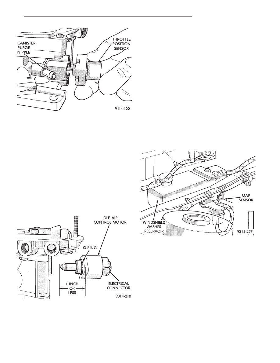
The idle air control motor is mounted on the throt-
tle body (Fig. 14).
REMOVAL
(1) Remove air cleaner.
(2) Disconnect negative cable from battery.
(3) Disconnect idle air control motor connector.
(4) Remove idle air control motor mounting screws
(Torx head screws, 25 mm long).
(5) Remove idle air control motor from throttle
body housing. Ensure O-ring was removed with idle
air control motor (Fig. 14).
INSTALLATION
(1) Ensure the idle air control motor pintle is in
the retracted position. If pintle measures more
than 1 inch (25 mm) as shown in Fig. 14, it must be
retracted. Use the DRBII scan tool Actuate Outputs
Test, IDLE AIR CONTROL MOTOR OPEN/CLOSE
(battery must be connected for this operation).
(2) Install new O-ring on idle air control motor.
(3) Install motor into housing, ensuring the O-ring
is in place.
(4) Tighten mounting screws to 2 N
Im (20 in. lbs.)
torque.
(5) Connect harness electrical connector to motor.
(6) Connect negative cable to battery.
MANIFOLD ABSOLUTE PRESSURE SENSOR
The MAP sensor is mounted underhood on the dash
panel (Fig. 15)
REMOVAL
(1) Remove vacuum hose and electrical connector
from sensor (Fig. 15).
(2) Remove sensor mounting screws. Remove sen-
sor.
(3) Reverse the above procedure for installation.
Check the vacuum hose and electrical connections to
the sensor.
CANISTER PURGE SOLENOID
(1) Remove vacuum hose and electrical connector
from solenoid (Fig. 16).
(2) Depress tab on top of solenoid and slide the so-
lenoid downward out of mounting bracket.
(3) Reverse the above procedure for installation.
ELECTRIC EXHAUST GAS RECIRCULATION
TRANSDUCER (EET) SERVICE
REMOVAL
(1) Disconnect the electrical connector from the
electronic EGR transducer solenoid (Fig. 17).
(2) Disconnect vacuum hoses.
INSTALLATION
(1) Connect vacuum hoses.
(2) Connect electrical connector.
Fig. 15 Manifold Absolute Pressure (MAP) Sensor
Fig. 13 Servicing Throttle Position Sensor
Fig. 14 Servicing Idle Air Control Motor
Ä
FUEL SYSTEMS
14 - 53