Chrysler Le Baron, Dodge Dynasty, Plymouth Acclaim. Manual - part 38


  Index      Chrysler     Chrysler Le Baron, Dodge Dynasty, Plymouth Acclaim - service repair manual 1993 year


Search            


Content   ..  36  37  38  39   ..


Chrysler Le Baron, Dodge Dynasty, Plymouth Acclaim. Manual - part 38


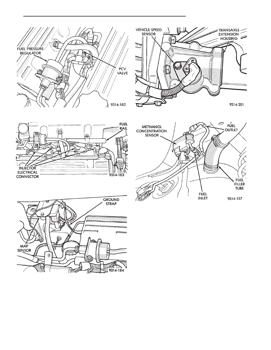
(18) Verify hose from PCV valve is securely at-

tached to the intake manifold vacuum port (Fig. 13).

(19) Check vacuum hose connection between vac-

uum source and fuel pressure regulator (Fig. 13).

(20) Inspect electrical connections at the fuel injec-

tors (Fig. 14).

(21) Inspect the heated oxygen sensor electrical

connector.

(22) Verify engine ground strap is attached to the

intake manifold and the dash panel (Fig. 15).

(23) Inspect all vacuum harness connections and

hoses for leaks.

(24) Verify the harness connector is attached to

the vehicle speed sensor (Fig. 16). Ensure the sensor
and connector are not damaged.

(25) Inspect hose and electrical connections at the

fuel pump. Ensure the electrical connector is fully
seated over the pump module terminals.

(26) Inspect electrical connections at the methanol

concentration sensor (Fig. 17).

Fig. 13 PCV Valve and Fuel Pressure Regulator

Fig. 14 Fuel Injector Electrical Connectors

Fig. 15 Ground Strap

Fig. 16 Vehicle Speed Sensor

Fig. 17 Methanol Concentration Sensor

Ä

FUEL SYSTEMS

14 - 69

2.5L FLEXIBLE FUEL MULTI-PORT FUEL INJECTION—ON-BOARD DIAGNOSTICS

INDEX

page

page

Circuit Actuation Test Mode

. . . . . . . . . . . . . . . . . 72

Diagnostic Trouble Codes . . . . . . . . . . . . . . . . . . . 71
General Information

. . . . . . . . . . . . . . . . . . . . . . . 70

High and Low Limits . . . . . . . . . . . . . . . . . . . . . . . 71
Ignition Timing Procedure

. . . . . . . . . . . . . . . . . . . 73

Monitored Circuits

. . . . . . . . . . . . . . . . . . . . . . . . 70

Non-Monitored Circuits

. . . . . . . . . . . . . . . . . . . . . 70

Powertrain Control Module 60-Way Connector

. . . 73

State Display Test Mode

. . . . . . . . . . . . . . . . . . . . 72

Throttle Body Minimum Air Flow Check Procedure

. . 73

GENERAL INFORMATION

The powertrain control module (PCM) monitors

many different circuits in the fuel injection system. If
the PCM senses a problem with a monitored circuit
often enough to indicate an actual problem, it stores a
diagnostic trouble code in the PCM’s memory. If the
problem is repaired or ceases to exist, the PCM cancels
the diagnostic trouble code after 51 vehicle key on/off
cycles.

Certain criteria must be met before the PCM stores a

diagnostic trouble code in memory. The criteria may be
a specific range of engine RPM, engine temperature,
and/or input voltage to the PCM.

The PCM might not store a diagnostic trouble code

for a monitored circuit even though a malfunction has
occurred. This may happen because one of the diagnos-
tic trouble code criteria for the circuit has not been met.
For example, assume the diagnostic trouble code
criteria for a certain sensor requires the PCM to
monitor the circuit only when the engine operates
between 750 and 2000 RPM. Suppose the sensor’s
output circuit shorts to ground when engine operates
above 2400 RPM (resulting in 0 volt input to the PCM).
Because the condition happens at an engine speed
above the maximum threshold (2000 rpm), the PCM
will not store a diagnostic trouble code.

There are several operating conditions for which the

PCM monitors and sets diagnostic trouble codes. Refer
to Monitored Circuits and Non-Monitored Circuits in
this section.

Technicians can display stored diagnostic trouble

codes by two different methods. The first is to cycle the
ignition switch On - Off - On - Off - On within 5
seconds. Then count the number of times the malfunc-
tion indicator lamp (check engine lamp) on the instru-
ment panel flashes on and off. The number of flashes
represents the trouble code. There is a slight pause
between the flashes representing the first and second
digits of the code. Longer pauses separate individual
trouble codes.

The second method of reading diagnostic trouble

codes uses the DRBII scan tool. The DRBII scan tool
connects to the data link (diagnostic) connector in the

vehicle (Fig. 1). For diagnostic trouble code informa-
tion, refer to charts in this section.

MONITORED CIRCUITS

The PCM can detect certain fault conditions in the

fuel injection system.

Open or Shorted Circuit - The PCM can determine

if the sensor output (input to the PCM) is within proper
range. Also, the PCM can determine open or shorted
circuits.

Output Device Current Flow - The PCM senses

whether output devices are hooked up. If a problem
exists within the circuit, the PCM senses whether the
circuit is open, shorted to ground, or shorted high.

Heated Oxygen Sensor - Once the system has

entered closed loop, the PCM determines if the oxygen
sensor is switching between rich and lean. Refer to
Modes of Operation in the General Information section
of this group for an explanation of closed loop opera-
tion.

NON-MONITORED CIRCUITS

The PCM does not monitor the following circuits,

systems and conditions that could have malfunctions
causing driveability problems. The PCM might not
store diagnostic trouble codes for these conditions.
However, problems with these systems may cause

Fig. 1 Data Link (Diagnostic) Connector

14 - 70

FUEL SYSTEMS

Ä

the PCM to store diagnostic trouble codes for other
systems. For example, a fuel pressure problem will not
register a fault directly, but could cause a rich or lean
condition. This could cause the PCM to store an oxygen
sensor diagnostic trouble code.

Fuel Pressure - The vacuum assisted fuel pressure

regulator controls fuel system pressure. The PCM
cannot detect a clogged fuel pump inlet filter, clogged
in-line fuel filter, stuck open regulator, or a pinched
fuel supply or return line. However, these could result
in a rich or lean condition causing the PCM to store an
oxygen sensor diagnostic trouble code.

Secondary Ignition Circuit - The PCM cannot

detect an inoperative ignition coil, fouled or worn spark
plugs, ignition cross firing, or open spark plug cables.

Engine Timing - The PCM cannot detect an incor-

rectly indexed timing belt, camshaft sprocket and
crankshaft sprocket. However, these could result in a
rich or lean condition causing the PCM to store an
oxygen sensor diagnostic trouble code.

Cylinder Compression - The PCM cannot detect

uneven, low, or high engine cylinder compression.

Exhaust System - The PCM cannot detect a

plugged, restricted or leaking exhaust system.

Fuel Injector Mechanical Malfunctions - The

PCM cannot determine if a fuel injector is clogged, the
needle is sticking or if the wrong injector is installed.
However, these could result in a rich or lean condition
causing the PCM to store an oxygen sensor diagnostic
trouble code.

Excessive Oil Consumption - Although the PCM

monitors exhaust stream oxygen content when the
system is in closed loop, it cannot determine excessive
oil consumption.

Throttle Body Air Flow - The PCM cannot detect a

clogged or restricted air cleaner inlet or filter element.

Evaporative System - The PCM cannot detect a

disconnected (open vacuum line) restricted, plugged or
loaded evaporative purge canister.

Vacuum Assist - The PCM cannot detect leaks or

restrictions in the vacuum circuits of vacuum assisted
engine control system devices. However, these could
cause the PCM to store a MAP sensor diagnostic
trouble code and cause a high idle condition.

PCM System Ground - The PCM cannot determine

a poor system ground. However, one or more diagnostic
trouble codes may be generated as a result of this
condition.

PCM Connector Engagement - The PCM may not

be able to determine spread or damaged connector
pins. However, it might store diagnostic trouble codes
as a result of spread connector pins.

HIGH AND LOW LIMITS

The PCM compares input signal voltages from each

input device with established high and low limits for the
device. If the input voltage is not within limits and other
criteria are met, the PCM stores a diagnostic trouble code
in memory. Other diagnostic trouble code criteria might
include engine RPM limits or input voltages from other
sensors or switches that must be present before verifying
a diagnostic trouble code condition.

DIAGNOSTIC TROUBLE CODES

A diagnostic trouble code indicates the powertrain

control module (PCM) has recognized an abnormal
condition in the system. Abnormal conditions are usu-
ally shorted or open circuits.

The technician can display diagnostic trouble codes in

two ways. The first way is to cycle the ignition switch and
count the number of times the malfunction indicator lamp
(check engine lamp on the instrument panel) flashes on
and off. The DRBII scan tool provides the second method
of displaying diagnostic trouble codes. Diagnostic trouble
codes indicate the results of a circuit failure, but do not
directly identify the failed component.

For a list of Diagnostic Trouble Codes, refer to

the charts at the end of this section.

OBTAINING DIAGNOSTIC TROUBLE CODES

USING DRBII SCAN TOOL

WARNING: APPLY PARKING BRAKE AND/OR BLOCK
WHEELS BEFORE PERFORMING ANY TEST ON AN
OPERATING ENGINE.

(1) Connect DRBII scan tool to the data link (diag-

nostic) connector located in the engine compartment,
next to the PCM (Fig. 1).

(2) If possible, start the engine and cycle the A/C

switch if applicable. Shut off the engine.

(3) Turn the ignition switch on, access Read Fault

Screen. Record all the diagnostic trouble codes shown on
the DRBII scan tool. [Observe the malfunction indicator
lamp (check engine lamp) on the instrument panel. The
lamp should light for 2 seconds then go out (bulb check)].

To erase diagnostic trouble codes, use the Erase

Trouble Code data screen on the DRBII scan tool.

USING THE MALFUNCTION INDICATOR LAMP

(1) Cycle the ignition key On - Off - On - Off - On

within 5 seconds.

(2) Count the number of times the malfunction indi-

cator lamp (check engine lamp on the instrument
panel) flashes on and off. The number of flashes
represents the trouble code. There is a slight pause be-

Ä

FUEL SYSTEMS

14 - 71

tween the flashes representing the first and second
digits of the code. Longer pauses separate individual
trouble codes.

(3) Refer to the Diagnostic Trouble Code Charts at

the end of this group.

STATE DISPLAY TEST MODE

The switch inputs to the powertrain control module

(PCM) have two recognized states; HIGH and LOW.
For this reason, the PCM cannot recognize the differ-
ence between a selected switch position versus an
open circuit, a short circuit, or a defective switch. If
the State Display screen shows the change from
HIGH to LOW or LOW to HIGH, assume the entire
switch circuit to the PCM functions properly. From
the state display screen, access either State Display
Inputs and Outputs or State Display Sensors.

STATE DISPLAY INPUTS AND OUTPUTS

Connect the DRBII scan tool to the vehicle and ac-

cess the State Display screen. Then access Inputs and
Outputs. The following is a list of the engine control
system functions accessible through the Inputs and
Outputs screen.
• Park/Neutral Switch (automatic transaxle only)

• Speed Control Resume

• Speed Control On/Off

• Speed Control Set

• Brake Switch

• A/C Switch Sense

• S/C Vent Solenoid

• S/C Vacuum Solenoid

• A/C Clutch Relay

• Auto Shutdown Relay

• Radiator Fan Relay

• (Duty Cycle) EVAP Purge Solenoid

• Malfunction Indicator (Check Engine) Lamp

STATE DISPLAY SENSORS

Connect the DRBII scan tool to the vehicle and ac-

cess the State Display screen. Then access Sensor
Display. The following is a list of the engine control
system functions accessible through the Sensor Dis-
play screen.
• Oxygen Sensor Signal

• Engine Coolant Temperature

• Engine Coolant Temp Sensor

• Throttle Position

• Minimum Throttle

• Battery Voltage

• MAP Sensor Reading

• Idle Air Control Motor Position

• Adaptive Fuel Factor

• Barometric Pressure

• Min Airflow Idle Spd (Speed)

• Engine Speed

• Fault #1 Key-On Info

• Module Spark Advance

• Speed Control Target

• Fault #2 Key-on Info

• Fault #3 Key-on Info

• Speed Control Status

• Charging System Goal

• Theft Alarm Status

• Battery Temperature

• Flex Fuel (Methanol Concentration) Sensor Volt-
age
• Methanol Content (percentage)

• Map Sensor Voltage

• Vehicle Speed

• Oxygen Sensor State

• MAP Gauge Reading

• Throttle Opening (percentage)

• Total Spark Advance

CIRCUIT ACTUATION TEST MODE

The Circuit Actuation Test Mode checks for proper

operation of output circuits or devices the powertrain
control module (PCM) cannot internally recognize.
The PCM attempts to activate these outputs and al-
low an observer to verify proper operation. Most of
the tests provide an audible or visual indication of
device operation (click of relay contacts, fuel spray,
etc.). Except for intermittent conditions, if a device
functions properly during testing, assume the device,
its associated wiring, and driver circuit work cor-
rectly.

OBTAINING CIRCUIT ACTUATION TEST

Connect the DRBII scan tool to the vehicle and ac-

cess the Actuators screen. The following is a list of
the

engine

control

system

functions

accessible

through Actuators screens. Subordinate screens for
each actuator test are also listed.

Stop All Tests
Ignition Coil No. 1
Fuel Injector No. 1
Fuel Injector No. 2
Fuel Injector No. 3
Fuel Injector No. 4
Idle Air Control Motor Open/Close
Fuel System
Radiator Fan Relay
A/C Clutch Relay
Auto Shutdown Relay
EVAP Purge Solenoid
Speed Control Servo Solenoids
Generator Field
Tachometer Output
Torque Converter Clutch Solenoid
All Solenoids/Relays
Speed Control Vent Solenoid
Speed Control Vacuum Solenoid
ASD Fuel System Test

14 - 72

FUEL SYSTEMS

Ä


Content   ..  36  37  38  39   ..