Chery B14. Manual - part 9


  Index      Chery     Chery B14 - service repair manual 2008 year


Search            


Content   ..  7  8  9  10   ..


Chery B14. Manual - part 9


  S

ervice Manual for Chery V525 Car                                                            Chassis 

4.2 Removal of rear axle assembly   

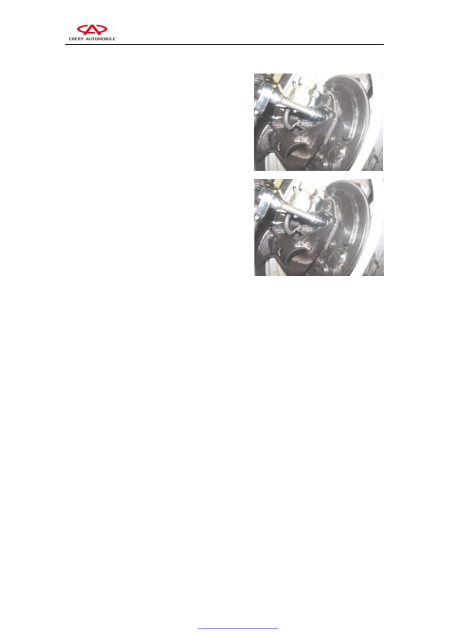
4.2.1Remove the four connecting bolts of rear axle 

  and brake assembly via 13# sleeve.     

Torque:    70±5N.m 


4.2.2 Remove the hinged bolts connecting rear axle and   

vehicle body via 17# sleeve. Then remove the rear axle.     

Torque: 110±10N.m 


5. Assembly procedures   

The assembly procedure is reverse to that of disassembly.     

Ⅲ. Adjustment of four-wheel alignment   

Please  use  four-wheel  alignment  gauge  as  recommended  by 

Chery  Company  to  carry  out  parameters  detection  and 

adjustment.     

1. Adjustment of front wheel toe-in   

Optic  test  instrument  or  mechanical  toe-in  regulator  can  be 

used for toe-in adjustment.     

1.1 In accordance with requirements for test instrument, make 

adjustment preparations for wheel alignment.     

1.2 Loosen the lock nut fastening rightward connecting tie rod 

and elastic ring, turn the toe-in regulation rod to adjust length 

as required to get prescribed value.   

Toe-in value: 10′±6′     

1.3  Fasten  the  lock  nut,  remount  circlip  of  the  jacket,  and 

check whether the lock nut is tightened, and ensure the jacket 

is in right position;     


  S

ervice Manual for Chery V525 Car                                                            Chassis 

Torque:    55±5N.m 

1.4  After  adjusting  toe-in  of  front  wheel,  check  whether  the 

steering wheel is horizontal. Otherwise, loosen the lock nut of 

steering  wheel,  adjust  steering  wheel  to  horizontal  position, 

and  tighten  up  the  lock  nut  of  steering  wheel  to  the  torque 

value as required.     

2. Adjustment of front-wheel camber angle   

2.1  Under  normal  condition,  it  is  unnecessary  to  adjust 

camber  angle  after  assembling  independent  suspension 

and  wheel  steering  knuckle,  if  found  camber  angle 

exceeds  tolerance  range  due  to  other  reasons,  the 

connecting  bolt  of  independent  suspension  and  steering 

knuckle can be used for adjustment. Front-wheel camber 

angle: - 30′±60′.     


2.2  Prior  to  adjustment,  check  (visual  inspection)  the 

parts of running system, and replace worn parts accordingly.     


2.3  If  found  front-wheel  camber  angle  exceeding  tolerance, 

loosen  the  connecting  bolt  fastening  shock  absorber  and 

steering knuckle, and move the wheel for rectification.     

3. Adjustment of kingpin caster angle   

Kingpin  caster  angle  guaranteed  by  designed  structure,  it  is 

unnecessary  to  adjust  in  service.  Kingpin  caster  angle: 

3.13°±1°,  if  parameters  exceed  prescribed  limit,  only  replace 

steering knuckle.     

4. Adjustment of rear wheel positional parameters   

All  of  the  rear  wheel  positional  parameters  shall  be 

guaranteed through design process.     

4.1 Rear wheel camber angle: 30′±30′.     


4.2 Rear wheel toe-in: 15′±15′.     


4.3  If  rear  wheel  positional  parameters  are  changed  and 

exceed  prescribed limit  due to rear axle  deformation resulted 

from  tremendous  impact  force,  it  can  only  be  remedied  via 

rectifying or replacing rear axle.     


  S

ervice Manual for Chery V525 Car                                                            Chassis 

Ⅳ.Installation of tire and regulation of air pressure   

1. Fit tire valve   

Prior  to  installing  tire  valve,  firstly  check  the  valve  port  to  ensure  whether  it  is  smooth  and  free 
from burr, and then apply glycerol on the rubber body surface, will soak the tire valve into glycerol. 
Pull or press (200 - 400N) using special tools to make the locating ring of the valve can go through 
the  wheel  holes,  to  this  point,  the  assembly  is  completed  (soap  water  is  allowed  to  substitute 
glycerol).     

2. Fit the tire   

Before fit the tire, apply glycerol or soap water along the cycle of tire bead, meanwhile, note that:       
2.1  When  there  is  colored  dot  on  the  wheel  rim,  align  the  uniformity  testing  mark  of  tire  to  the 
colored dot mark of wheel rim.       
2.2 When without  colored  dot  on the wheel rim, align the dynamic balance testing  mark  of tire to 
valve position.     
2.3 When  without colored dot  on the  wheel rim, additionally, there is  no dynamic balance testing 
mark, however, static balance testing mark is available, at this point, align the tire valve to the static 
balance testing mark.     
2.4  The  description  concerning  the  uniformity,  dynamic  balance  and  static  balance  testing  marks 
for  tires  will  be  additionally  provided  in  writing  by  the  product  division  of  Chery  Company  or 
suppliers. In addition, this kind of descriptions will clearly be indicated on process sheet.     
2.5 Carry out tire inflation strictly in accordance with specified pressure. During inflating process, 
air pressure shall not exceed 10% of rated pressure. When performing separate packaging to spare 
wheel assembly, the rated inflation pressure shall be 3.5bar, and the spare wheel assembly shall be 
stored  separately  from  four  wheels.  Prior  to  carrying  out  four-wheel  alignment,  check  four-wheel 
tire pressure and adjust air pressure. Front wheel pressure shall be 2.0±0.2 bar; the rear wheel shall 
be 2.2± 0.2bar.     

3. Tire inflation   

After completion of tire inflation, screw up the protective cap of valve, and then carry out dynamic 
balancing  test.  Fit  appropriate  balance  weight  at  the  internal  and  external  fringe  of  wheel  rim  as 
required.  It  is  required  that  the  unbalancedness  of  the  final  assembly  shall  be  less  than  100g·cm, 
which  is  approximately  equivalent  to  a  5g  balance  weight  at  the  internal  and  external  fringe  of 
wheel rim.   
Note: each wheel and each side can use only one balance weight. Additionally, its maximum mass 
shall  not  be  more  than  70g.  During  assembling  process,  never  hit  the  balance  weight  too  heavy. 
Otherwise,  replace  balance  weight  in  time.  In  addition,  never  use  the  replaced  balance  weight 
again.     

4. Installation of wheel and tire assembly   

When  fixing  wheel  and  tire  assembly,  first,  manually  screw  up  the  wheel  bolt  onto  the  hub  for 
pretension,  after  that  use  special  tools  for  tightening  in  accordance  with  diagonal  process. 
Tightening torque shall be 110±10N.m. It is prohibited to use impact wrench to prevent from wheel 
damage,  over  loose  or  over  tight.  It  is  not  allowed  to  apply  grease  on  wheel  bolt  (For  newly 
assembled wheel and tire assembly, after initial 100km traveling, it is required to tighten the wheel 
bolts  once  to  guarantee  appropriate  tightening  torque,  and  the  inspection  of  wheel  bolt  tightening 
torque is one of the routine maintenances).     

5. Tightening method of wheel nut   

Tighten  the  fixing  nut  in  a  decussate  way,  the  tightening  force  shall  be  approximately  equal,  then 
wheel shall be able to turn freely. When carry out final tightening, the wheel shall be on the ground.     

6. Assembly of trim cover   

Mount trim cover or place trim cover as required.    When fitting clip- type trim cover, place knock 
in position by hand or via rubber tools.     


  S

ervice Manual for Chery V525 Car                                                            Chassis 

Chapter Three Disassembly, Assembly and Overhaul of Steering 

System 

Ⅰ. Disassembly and assembly of steering gear   

1. System structural diagram   


1. Power steering reservoir 

2. Bracket fixing bolt 

3. Bracket fixing nut 

4.Oil outlet pipe 

5. Fixing bracket of reservoir 

6. Steering pump 

7. Tension pulley 

8. Self-locking nut 

9. Adjusting nut 

10. Regulating pull rod 

11. Pipe clip 

12.Steering gear 

13. Oil outlet pipe 

14, 15. Fixing bolt 

16. Fixing nut 

17. Oil return pipe 


System Structural diagram 

2. Preparation   

Tools: screwdriver, 8#, 10#, 13#, 18#, 19# sleeve, 5# hexagon 

socket spanner.     

Accessories: power steering fluid   


Content   ..  7  8  9  10   ..