Volvo V60 Plug-in Hybrid (2015 year). Instruction - part 21


  Index      Volvo     Volvo V60 Plug-in Hybrid - instruction 2015 year in english


Search            


Content   ..  19  20  21  22   ..


Volvo V60 Plug-in Hybrid (2015 year). Instruction - part 21


10 Maintenance and service

10

355

IMPORTANT

A high content of chlorine, chlorides

and other salts may cause corrosion in

the cooling system.

Always use coolant with anti-corrosion

agent as recommended by Volvo.

Ensure that the coolant mixture is 50%

water and 50% coolant.

Mix the coolant with approved quality

tap water. In the event of any doubt

about water quality, used ready-mixed

coolant in accordance with Volvo rec-

ommendations.

When changing coolant/replacing

cooling system components, flush the

cooling system clean with approved

quality tap water or flush with ready-

mixed coolant.

The engine must only be run with a

well-filled cooling system. Otherwise,

temperatures that are too high may

occur resulting in the risk of damage

(cracks) in the cylinder head.

Brake and clutch fluid - level

The brake fluid level should be between con-

tainer's MIN and MAX marks.

Checking the level
The level must be between the MIN and MAX

marks that are visible inside the reservoir.

Check the level regularly.
Change the brake fluid every other year or at

every other regular service.
The fluid should be changed annually on cars

driven in conditions requiring hard, frequent

braking, such as driving in mountains or tropi-

cal climates with high humidity.
For capacities and recommended brake fluid

grade, see Brake fluid - grade and volume

(p. 405).

WARNING

If the brake fluid is under the MIN level in

the brake fluid reservoir, do not drive fur-

ther before topping up the brake fluid.

Volvo recommends that the reason for the

loss of brake fluid is investigated by an

authorised Volvo workshop.

Filling

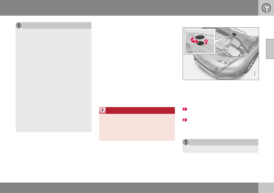
The fluid reservoir is located on the driver's side.

The fluid reservoir is protected under the

cover over the cold zone in the engine com-

partment. The round cover must be removed

first before the reservoir cap can be reached.

Turn and open the cover located on the

covering.
Unscrew the reservoir cap and fill the

fluid. The level must be between the MIN

and MAX marks, which are located on

the inside of the reservoir.

IMPORTANT

Do not forget to refit the cap.

10 Maintenance and service

10

356

Power steering fluid - level

The power steering fluid level must be

between the reservoir's MIN and MAX marks.

The fluid does not need to be changed.

IMPORTANT

Keep the area around the power steering

fluid reservoir clean when checking. The

cover must not be opened.

Check the level frequently. The fluid does not

require changing. The level must be between

the MIN and MAX marks.
For recommended fluid grade, see Power

steering fluid - grade (p. 405).

NOTE

If a fault should arise in the power steering

system, or if the engine is switched off and

must be towed, then the car can still be

steered.

Climate control system - fault tracing

and repair

The air conditioning system must only be

serviced and repaired by an authorised work-

shop.

Troubleshooting and repair
The air conditioning system contains fluores-

cent tracing agents. Use ultraviolet light when

looking for leaks.
Volvo recommends that you contact an

authorised Volvo workshop.

WARNING

The air conditioning system contains pres-

surised refrigerant R134a. This system

must only be serviced and repaired by an

authorised workshop.

Related information

Volvo service programme (p. 345)

10 Maintenance and service

10

357

Lamp replacement - general

Lamp replacement can be carried out for

bulbs. When replacing LED and Xenon lamps,

please refer to a workshop.

The bulbs are specified (p. 363). The follow-

ing list contains locations of bulbs and other

light sources that are specialised, such as
LED

5

 lamps, or are unsuitable for changing

for some other reason, except at a work-
shop

6

:

Active Xenon headlamps - ABL (Xenon

lamps)

Daytime running lights/Position/parking

lamps front

Cornering lights

Side direction indicators, door mirrors

Approach lighting, door mirrors

Interior lighting apart from Courtesy light-

ing front

Position/parking lamps rear

Side marker lamps

Brake light.

WARNING

On cars with Xenon headlamps, the

replacement of Xenon lamps must be car-

ried out at a workshop - an authorised

Volvo workshop is recommended. Working

with Xenon lamps demands extreme cau-

tion because the headlamp is equipped

with a high voltage unit.

WARNING

The car's electrical system must be in key

position 0 for bulb replacement; see Key

positions - functions at different levels

(p. 81).

IMPORTANT

Never touch the glass part of the bulbs

with your fingers. Grease from your fingers

is vaporised by the heat, coating the

reflector and then causing damage.

NOTE

If an error message remains after the bro-

ken bulb has been replaced then we rec-

ommend that you visit an authorised Volvo

workshop.

NOTE

Outside lighting such as headlamps, fog

lamps and rear lamps may temporarily

have condensation on the inside of the

lens. This is normal, all exterior lighting is

designed to withstand this. Condensation

is normally vented out of the lamp housing

when the lamp has been switched on for a

time.

Related information

Lamp replacement - headlamps (p. 358)

Lamp replacement - location of rear

lamps (p. 362)

Lamp replacement - vanity mirror lighting

(p. 363)

Lamp replacement - lighting in cargo area

(p. 362)

Lamp replacement - number plate lighting

(p. 362)

5

LED (Light Emitting Diode)

6

An authorised Volvo workshop is recommended.

10 Maintenance and service

10

358

Lamp replacement - headlamps

All of the headlamp bulbs are replaced via the

engine compartment. First loosen and remove

the whole headlamp.

Removing the headlamp
Set the car's electrical system in key position

0, see Key positions - functions at different

levels (p. 81).

Pull out the headlamp's locking pins.

Release the headlamp by alternately tilt-

ing and pulling it out.

IMPORTANT

Do not pull the electrical cable, only the

connector.

Detach the headlamp connector by

pressing down the clip with your thumb.
At the same time, guide out the connec-

tor with your other hand.

5. Lift out the headlamp and place it on a

soft surface to avoid scratching the lens.

6. Replace the bulb in question.

Securing the headlamp

1. Plug in the connector, a clicking sound

should be heard.

2. Reinstall the headlamp and locking pins.

The short pin is fitted closest to the grille.

Check that they are firmly inserted.

3. Check the lighting.
The headlamp must be mounted and the con-

nector firmly connected before the lighting is

switched on or the remote control key is

inserted into the ignition switch.

Related information

Lamp replacement - general (p. 357)

Lamp replacement - cover for main/

dipped beam bulbs (p. 359)

Lamps - specifications (p. 363)

10 Maintenance and service

10

359

Lamp replacement - cover for main/

dipped beam bulbs

Main/dipped beam bulbs are accessed by

releasing the headlamp's larger cover.

Before starting to replace a bulb, see Lamp

replacement - headlamps (p. 358).
1. Unscrew the cover's four screws using a

Torx tool, size T20 (1). They should not be

loosened completely. (3 - 4 turns are suf-

ficient.)

2. Slide the cover to one side.
3. Remove the cover.
Reinstall the cover in reverse order.

Related information

Lamp replacement - headlamps (p. 358)

Lamp replacement - dipped beam

(p. 359)

Lamp replacement - main beam (p. 360)

Lamp replacement - extra main beam

(p. 360)

Lamp replacement - dipped beam

The dipped beam bulb is fitted inside the

headlamp's larger cover.

NOTE

Applies to cars with halogen headlamps.

1. Detach the headlamp (p. 358).
2. Remove the cover (p. 359).
3. Unplug the connector from the bulb.
4. Detach the bulb by pulling it straight out.
5. The guide pin on the lamp should be

straight up when it is fitted and a clicking

sound should be heard when it clicks into

place.

Reinstall the parts in reverse order.

Related information

Lamps - specifications (p. 363)

10 Maintenance and service

10

360

*


Option/accessory, for more information, see Introduction.

Lamp replacement - main beam

The main beam bulb is fitted inside the head-

lamp's larger cover.

NOTE

Applies to cars with halogen headlamps.

1. Detach the headlamp (p. 358).
2. Remove the cover (p. 359).
3. Detach the bulb by turning anticlockwise

and then pulling straight out.

4. Unplug the connector from the bulb.
5. Replace the bulb and align it in the socket

and turn clockwise in order to secure it. It

can only be secured in one position.

Reinstall the parts in reverse order.

Related information

Lamps - specifications (p. 363)

Lamp replacement - extra main beam

The extra main beam bulb is fitted inside the

headlamp's larger cover.

NOTE

Applies to cars with Xenon headlamps*.

1. Detach the headlamp (p. 358).
2. Remove the cover (p. 359).
3. Detach the bulb by turning anticlockwise

and then pulling straight out.

4. Unplug the connector from the bulb.
5. Replace the bulb and align it in the socket

and turn clockwise in order to secure it. It

can only be secured in one position.

Reinstall the parts in reverse order.

Related information

Lamps - specifications (p. 363)

Lamp replacement - direction

indicators front

The direction indicator lamp is fitted inside

the headlamp's smaller cover.

1. Detach the headlamp (p. 358).
2. Detach the cover by pulling it straight out.
3. Pull the bulb holder in order to extract the

bulb.

4. Press and simultaneously turn the bulb

anticlockwise in order to detach it.

Reinstall the parts in reverse order.

Related information

Lamps - specifications (p. 363)

10 Maintenance and service

10

361

Lamp replacement - rear lamp

Rear direction indicators, rear fog lamp and

reversing lamp are replaced from inside the

cargo area.

Lamp housing, rear

The bulbs for reversing lamp, fog lamp and

direction indicator in the rear lamp cluster are

replaced from inside the cargo area.

The lamps are accessible when emergency

puncture repair kit is lifted out.

1. Open the panel.
2. Lift the emergency puncture repair kit.
3. Remove the insulation that is fitted in

front of the bulb holder by pulling it

straight out.

4. Press down the catch and pull out the

bulb holder.

5. Remove the blown bulb by pressing it in

and turning anticlockwise.

6. Fit a new bulb, press down and turn

clockwise.

7. Press down the catch when the bulb

holder is refitted.

8. Refit the insulation, emergency puncture

repair kit and panel.

Related information

Lamp replacement - location of rear

lamps (p. 362)

Lamps - specifications (p. 363)

10 Maintenance and service

10

362

Lamp replacement - location of rear

lamps

The overview shows the location of the lamps

at the rear.

Brake light (LED)

Position/parking lamps (LED)/Side marker

lamps (LED)
Indicator (p. 361)

Brake light (LED)

Reversing lamp

Fog lamps

Related information

Lamp replacement - general (p. 357)

Lamps - specifications (p. 363)

Lamp replacement - number plate

lighting

The number plate lighting is located under the

tailgate handle.

1. Remove the screws with a screwdriver.
2. Carefully detach the whole lamp housing

and withdraw it.

3. Replace the bulb.
4. Refit the whole lamp housing and screw it

into place.

Related information

Lamps - specifications (p. 363)

Lamp replacement - lighting in cargo

area

The cargo area lighting is located in the tail-

gate.

G031942

1. Insert a screwdriver and gently prize so

that the lamp housing comes loose.

2. Replace the bulb.
3. Check that the bulb illuminates and press

back the lamp housing.

Related information

Lamps - specifications (p. 363)

10 Maintenance and service

10

}}

363

Lamp replacement - vanity mirror

lighting

The vanity mirror's lamps are fitted inside the

lamp lenses.

Removal of lamp lens

1. Insert a screwdriver under the lamp lens

and gently prize up the lug on the edge.

2. Carefully detach and lift aside the lamp

lens.

3. Use needle-nose pliers to pull the bulb

straight out to the side and replace with a

new one. Note! - Do not pinch hard with

the pliers. Otherwise the lamp lens could

then be crushed.

Attaching the lamp lens
1. Refit the lamp lens.
2. Press it into place.

Related information

Lamps - specifications (p. 363)

Lamps - specifications 

The specifications apply to bulbs. When

replacing LED and Xenon lamps, please refer

to a workshop.

Lighting

W

A

Type

Dipped beam,

halogen

55

H7 LL

Main beam, Halo-

gen

65

H9

Extra main beam,

ABL

65

H9

Front direction

indicators

24

PY24W

Courtesy lighting

front

3

T10 Socket

W2.1x9.5d

Glovebox lighting

5

Socket SV8.5

Length 43 mm

Vanity mirror

lighting

1.2

T5 Socket

W2x4.6d

Cargo area light-

ing

5

Socket SV8.5

Length 43 mm

Number plate

lighting

5

C5W LL

Direction indica-

tors, rear

21

PY21W LL

||

10 Maintenance and service

10

364

Lighting

W

A

Type

-

-

-

Reversing lamp

21

P21W LL

Rear fog lamp

21

H21W LL

A

Watt

Related information

Lamp replacement - general (p. 357)

Lamp replacement - location of rear

lamps (p. 362)

Lamp replacement - vanity mirror lighting

(p. 363)

Wiper blades

The wiper blades sweep water away from the

windscreen and rear window. Together with

the washer fluid they clean the windows and

ensure visibility for driving.
The windscreen wiper blades must be in serv-

ice position when they are to be replaced.

Service position

Wiper blades in service position.

In order to change, clean or lift the wiper

blades (for scraping off ice from the wind-

screen, for example) they must be in service

position.

IMPORTANT

Before placing the wiper blades in the

service position, make sure that they are

not frozen down.

1. Insert the remote control key in the igni-

tion switch

7

 and briefly press the START/

STOP ENGINE button to set the car's

electrical system to key position I. For

detailed information on key positions, see

Key positions - functions at different lev-

els (p. 81).

2. Briefly press the START/STOP ENGINE

button again to set the car’s electrical

system in key position 0.

3. Within 3 seconds, move the right stalk

switch up and hold it in position for

approx. 1 second.
> The wipers then move to standing

straight up.

The wipers return to their starting position

when you briefly press the START/STOP

ENGINE button to set the car’s electrical sys-

tem to key position I (or when the car is

started).

7

Not necessary in cars with the Keyless function.

10 Maintenance and service

10

}}

365

IMPORTANT

If the wiper arms in service position have

been folded up from the windscreen, they

must be folded back down onto the wind-

screen before the wipers are allowed to

return to their starting position. This is to

avoid scraping the paint on the bonnet.

Replacing the wiper blades

Fold up the wiper arm when it is in serv-

ice position. Press the button located on

the wiper blade mounting and pull

straight out parallel with the wiper arm.
Slide in the new wiper blade until a "click"

is heard.
Check that the blade is firmly installed.

4. Fold the wiper arm back towards the

windscreen.

The wipers return from service position to

their starting position when you briefly press

the START/STOP ENGINE button to set the

car’s electrical system to key position I (or

when the car is started).

NOTE

The wiper blades are different lengths. The

blade on the driver's side is longer than on

the passenger side.

Replacing the wiper blades, rear
window

||

10 Maintenance and service

10

366

1. Fold out the wiper arm.
2. Grip the inner section of the blade (by the

arrow).

3. Turn anticlockwise to use the blade's end

position against the wiper arm as a lever

to detach the blade more easily.

4. Press the new wiper blade into position.

Check that it is firmly installed.

5. Lower the wiper arm.

Cleaning
For cleaning wiper blades and windscreen,

see Car wash (p. 386).

IMPORTANT

Check the blades regularly. Neglected

maintenance shortens the service life of

the wiper blades.

Related information

Washer fluid - filling (p. 366)

Washer fluid - filling

Washer fluid is used for cleaning the head-

lamps and windows. Washer fluid with anti-

freeze must be used during winter.

The windscreen and headlamp washers share

a common reservoir.

IMPORTANT

Use Volvo genuine washer fluid or equiva-

lent with a recommended pH of between 6

and 8, in working dilution (e.g. 1:1 with

neutral water).

IMPORTANT

Use washer fluid with antifreeze during the

winter to avoid freezing in the pump, reser-

voir and hoses.

For capacities, see Washer fluid - quality and

volume (p. 405).

Related information

Wiper blades (p. 364)

10 Maintenance and service

10

}}

367

Starter battery - general

The starter battery is used to drive the starter

motor and other electrical equipment in the

car.

The car's traditional 12 V battery is here

called "starter battery" even if the hybrid bat-

tery (p. 371) is often used for starting the

internal combustion engine.
The service life and function of the starter

battery is influenced by factors such as the

number of starts, discharging, driving style,

driving conditions, climatic conditions, etc.

Never disconnect the starter battery when

the engine is running.

Check that the cables to the starter bat-

tery are correctly connected and properly

tightened.

Voltage (V)

12

Cold start capacity

A

 -

CCA

B

 (A)

760

Size, L×W×H (mm)

278×175×190

Capacity (Ah)

70

A

In accordance with EN standard.

B

Cold Cranking Amperes.

IMPORTANT

When replacing the starter battery, in cars

with Start/Stop function, a battery of the

correct type must be fitted, EFB

8

 in cars

with manual gearbox and AGM

9

 in cars

with automatic gearbox.
When replacing the support battery, a bat-

tery of AGM type must be fitted.

IMPORTANT

If the starter battery is replaced, make sure

you replace it with a battery with the same

cold starting capacity and type as the orig-

inal battery (see the label on the battery).

NOTE

The starter battery's container size

should be consistent with the original

battery's dimensions.

The starter battery's height is different

depending on size.

WARNING

The battery can generate oxyhydrogen

gas, which is highly explosive. A spark

can be formed if a jump lead is con-

nected incorrectly, and this can be

enough for the battery to explode.

The battery contains sulphuric acid,

which can cause serious burns.

If sulphuric acid comes into contact

with eyes, skin or clothing, flush with

large quantities of water. If acid

splashes into the eyes - seek medical

attention immediately.

IMPORTANT

When charging the starter battery, only

use a modern battery charger with con-

trolled charging voltage. Fast charging

function must not be used since it may

damage the battery.

NOTE

If both the starter battery and the hybrid

battery (p. 292) are discharged then both

batteries must be charged. In such a case,

charging only the hybrid battery first is not

possible.

8

Enhanced Flooded Battery.

9

Absorbed Glass Mat.

||

10 Maintenance and service

10

368

IMPORTANT

If the following instruction is not observed

then the energy saving function for info-

tainment system may be temporarily dis-

engaged, and/or the message in the com-

bined instrument panel's information dis-

play about the starter battery's state of

charge may be temporarily inapplicable,

following the connection of an external

starter battery or battery charger:

The negative battery terminal on the

car's starter battery must never be

used for connecting an external starter

battery or battery charger - only the

car chassis may be used as the

grounding point.

See Jump starting with battery (p. 261) for

a description of how the cable clamps

must be attached.

NOTE

The life of the battery is shortened if it

becomes discharged repeatedly.
The life of the battery is affected by several

factors, including driving conditions and

climate. Battery starting capacity decrea-

ses gradually with time and therefore

needs to be recharged if the car is not

used for a longer time or when it is only

driven short distances. Extreme cold fur-

ther limits starting capacity.
To maintain the battery in good condition,

at least 15 minutes of driving/week is rec-

ommended or that the battery is con-

nected to a battery charger with automatic

trickle charging.
A battery that is kept fully charged has a

maximum service life.

Related information

Battery - symbols (p. 368)

Starter battery - replacement (p. 369)

Battery - symbols

There are information and warning symbols

on the battery.

Symbols on the battery

Use protective goggles.

Further information in the

owner's manual for the

car.

Store the battery out of

the reach of children.

The battery contains cor-

rosive acid.

10 Maintenance and service

10

}}

369

Avoid sparks and naked

flames.

Risk of explosion.

Must be taken for recy-

cling.

NOTE

An expended battery must be recycled in

an environmentally safe manner as it con-

tains lead.

Related information

Starter battery - general (p. 367)

Starter battery - replacement

The starter battery in the car can be replaced

without the help of a workshop.

The car's traditional 12 V battery is here

called "starter battery" even if the hybrid bat-

tery (p. 371) is often used for starting the

internal combustion engine.

Removal
First of all
: Take the remote control key from

the ignition switch and wait at least 5 minutes

before any electrical connections are touched

- this is because the car's electrical system

needs to store the necessary information to

control modules.

||

10 Maintenance and service

10

370

Open the clips on the front cover and

remove the cover.
Release the rubber moulding so that the

rear cover is free.
Remove the rear cover by screwing one

quarter turn and lifting it away.

WARNING

Connect and remove the positive and neg-

ative cables in the correct order.

Detach the black negative cable.

Detach the red positive cable.

Detach the ventilation hose from the bat-

tery.
Loosen the screw holding the battery

clamp.

Move the battery aside.

Lift it up.

Fitting

1. Lower the battery into the battery box.
2. Move the battery inward and to the side

until it reaches the rear edge of the box.

3. Tighten the clamp that holds the battery.
4. Connect the ventilation hose.

> Check that it is correctly connected to

both battery and outlet in the body.

5. Connect the red positive cable.
6. Connect the black negative cable.
7. Press in the rear cover. (See earlier sec-

tion "Removal".)

8. Fit the rubber moulding. (See "Removal".)
9. Align the front cover and secure it with

the clips. (See "Removal".)

For more information on the car's starter bat-

tery, see Jump starting with battery (p. 261).


Content   ..  19  20  21  22   ..