Volvo 50-42LE transmission. Manual - part 20
 

  Index      Volvo     Volvo 50-42LE transmission - service repair manual 2004 year


Search            


Content   ..  18  19  20  21   ..


Volvo 50-42LE transmission. Manual - part 20


AUTOMATIC TRANSMISSION SERVICE GROUP

Technical Service Information

79

153. Remove the bearing race and the two 30 torx
        bolts retaining the C1 accumulator cover.
        Caution: The cover is spring loaded. Note: 
        The bolt lengths are 14mm. 
Once the cover is
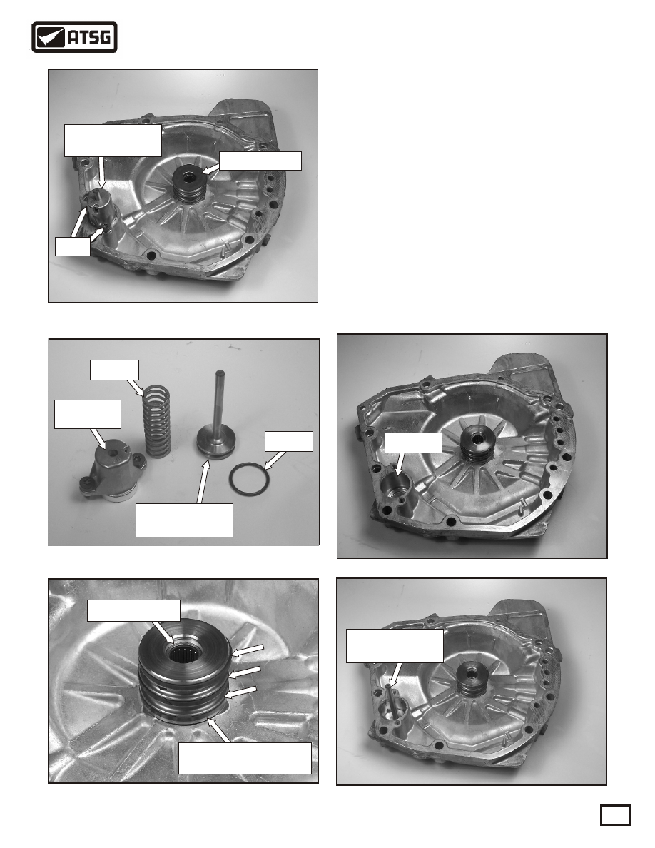
        off, remove the spring and piston from the 
        cover. See Figure 211.
154. See Figure 212 for a view of the accumulator 
        assembly completely dis-assembled.
155. Inspect the needle bearing in the rear cover and
        replace the three sealing rings as shown in
        Figure 213. Note: The early design rear cover
        has an aluminum sleeve which requires steel
        sealing rings. ATSG recommends the late 
        design, which is the steel sleeve.
156. Lubricate the rear cover  shown in Figure 214,
        replace the C1 accumulator piston o-ring and 
        install it into the rear cover. See Figure 215.

Figure 214

Figure 212

Figure 211

Figure 215

Figure 213

Copyright © 2004 ATSG

Needle bearing

C1 accumulator

cover

Crush sleeve

Bearing race

Lock nut

SUB-ASSEMBLIES

"REAR COVER"

C1 accumulator

piston

O-ring

Cover and

bolts

Spring

Steel sleeve uses

3 Teflon sealing rings

Lubricate

C1 accumulator

piston

Bolts

Continued on Page 80

AUTOMATIC TRANSMISSION SERVICE GROUP

Technical Service Information

80

157. Install the C1 accumulator spring over the 
        accumulator piston as shown in Figure 216.
158. Assemble the C1 accumulator cover into the 
        rear cover and torque the 30 torx bit bolts to
        70-100 in. lb. See Figure 217. 
159. Install the Bearing race, using some assembly 
        grease. See Figure 218. 
160. Place the C1 / C2 drum onto the rear cover and
        air check the clutches using 80-100psi. of air 
        pressure.  See Figure 219. Refer to Figure 220
        to identify the air check ports.

Figure 217

Figure 218

Figure 216

C1 accumulator

spring

Bearing race

"A"

SUB-ASSEMBLIES

"REAR COVER Contd."

C1 accumulator

cover

Bolts

"B"

"C"

"D"

Figure 219

Figure 220

"A"= C1 clutch

C1/C2 AIR CHECKS

"B"= C2 clutch

"C"= lube

"D"= C1 clutch

Note: When air checking the C1 clutch thru
          the D port, you must cover the A port
          and vice-versa. The C1 accumulator
          will stroke when the C1 clutch is applied.

AUTOMATIC TRANSMISSION SERVICE GROUP

Technical Service Information

81

VALVE BODY EXPLODED VIEWS

AND IDENTIFICATION OF COMPONENTS

 Refer to Figure 221 for Solenoid identification and locations on the valve body.

 Refer to Figure 222 for valve identification and locations in the "Upper" valve body.

 Refer to Figure 223 for valve identification and locations in the "Center" valve body, "Front" side.

 Refer to Figure 224 for valve identification and locations in the "Center" valve body, "Rear" side.

 Refer to Figure 225 for valve identification and locations in the "Lower" valve body, "Front" side.

 Refer to Figure 226 for valve identification and locations in the "Lower" valve body, "Rear" side.

 Refer to Figure 227 for illustrations of the typical spacer plates.

 Refer to Figure 228 for the check valve and check ball locations in the "Lower" valve body.

 Refer to Figure 229 for the screen locations in the "Center" valve body, "Upper" valve body side.

 Refer to Figure 230 for the check valve and check ball locations in the "Center" valve body, "Lower"
 valve body side.

Refer to Figure 231 for bolt identification and locations for the "Lower" valve body.

SUB-ASSEMBLIES

AUTOMATIC TRANSMISSION SERVICE GROUP

Technical Service Information

82

99

99

22

2 2

2 2

11

9

1

1

5

2

B

1

9
B

1

9

Shift Solenoid

Number 1

Shift Solenoid

Number 2

Pressure Control

Solenoid

TCC Solenoid

Figure 221

SOLENOID IDENTIFICATION

AND BOLT LOCATIONS

8mm Head

10mm long

8mm Head

35mm long

8mm Head

10mm long

8mm Head

35mm long

Pressure control

solenoid retainer


Content   ..  18  19  20  21   ..