Volvo 50-42LE transmission. Manual - part 18
AUTOMATIC TRANSMISSION SERVICE GROUP
Technical Service Information
71
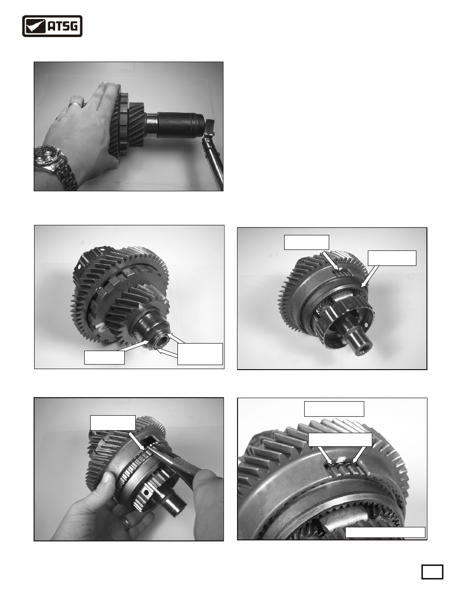
116. Tighten the lock nut until the turning torque is
between 5-12 in.lb. See Figure 171. Note:
To check turning torque, hold the counter
driven gear with the left hand and check the
turning torque with an inch pound torque
wrench with the right hand.
117. Using a punch, stake the nut on both sides of
the shaft, as shown in Figure 172.
118. Using needle nose pliers, compress the tabs of
the snap ring towards the ring gear and push it
into the back of the counter driven gear shown
in Figure 173.
119. Push the ring gear into the counter driven gear
until it snaps into it's groove. See Figure 174
and the close-up in Figure 175.
Figure 153
Figure 174
Snap ring
Ring gear
Figure 172
Copyright © 2004 ATSG
Lock nut
Stake with
punch
Figure 171
CLOSE-UP
Snap ring tabs
Figure 175
Figure 173
Copyright © 2004 ATSG
Snap ring
SUB-ASSEMBLIES
"UNDERDRIVE PLANETARY AND
DIFFERENTIAL PINION GEAR ASSY. Contd."