Volvo 50-42LE transmission. Manual - part 19
 

  Index      Volvo     Volvo 50-42LE transmission - service repair manual 2004 year


Search            


Content   ..  17  18  19  20   ..


Volvo 50-42LE transmission. Manual - part 19


AUTOMATIC TRANSMISSION SERVICE GROUP

Technical Service Information

75

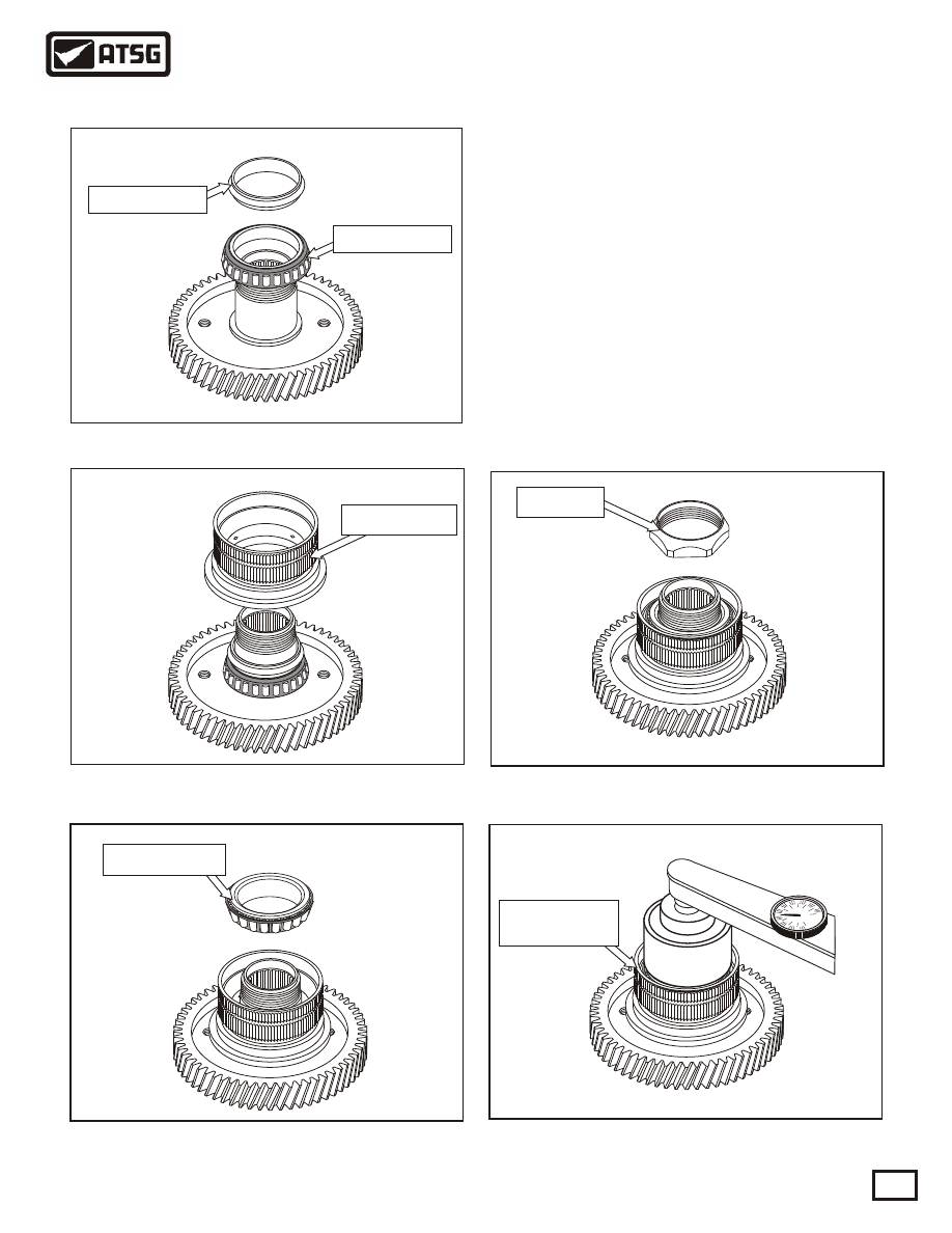
135. Press the rear bearing onto the counter drive 
        gear and place a new crush sleeve on the top of
        the rear bearing as shown in Figure 191.
136. Assemble the bearing race on top of the rear
        bearing as shown in Figure 192.
137. Press the Front bearing onto the counter drive
        gear shaft as shown in Figure 193.
138. Place a new lock nut on to the counter drive 
        gear and snug it down. See Figure 194.
139. Place the counter drive gear into a suitable
        holding fixture or vice and tighten the lock nut 
        down until turning torque is approximately 3-7 
        in.lb. See Figure 195. Refer  to Figure 186 and
        stake the lock nut in two places. 

Figure 194

Figure 192

Figure 191

Figure 195

Figure 193

Copyright © 2004 ATSG

Front bearing

Crush sleeve

Crush sleeve

Crush sleeve

Rear bearing

Bearing race

Lock nut

1

0

2

9

3

8

4

7

5

6

10

Hold bearing

race

SUB-ASSEMBLIES

"COUNTER DRIVE GEAR Contd."

AUTOMATIC TRANSMISSION SERVICE GROUP

Technical Service Information

76

140. Remove the snap ring and C1 clutch assembly
        as shown in Figure 196.
141. Remove the snap ring and C2 clutch assembly
        as shown in Figure 197.
142. Using a suitable press, remove the snap ring
        and return spring  as shown in Figure 198.
143. Remove the C1 and C2 pistons from the drum
        as shown in Figure 199. 
144. Refer to Figure 200 for a view of the complete
        assembly dis-assembled.

Figure 199

Figure 197

Figure 200

Figure 198

SUB-ASSEMBLIES

"C1 / C2 DRUM"

Snap ring and return spring

C1/C2 drum

Continued on Page 77

Figure 196

Inner race

Snap ring

C1 clutch assy.

Snap ring

C2 clutch assy.

Return spring

Snap ring

C1 piston

C2 piston

C1 piston

C1 clutch

C2 clutch

C2 piston

AUTOMATIC TRANSMISSION SERVICE GROUP

Technical Service Information

77

145. Inspect the rear of the C1/C2 drum where the 
        weld is to ensure there are no visible cracks.
        Replace the sealing ring shown in Figure 201.
        Note: This drum is notorious for cracking.
146. Inspect the check ball in the C1 piston for 
        debris and replace the inner and outer piston
        o-rings as shown in Figure 202.
147. Lubricate the inner and outer o-rings, and the
        area where they ride in the drum, and install
        the C1 piston. See Figure 203.
148. Inspect the check ball in the C2 piston for 
        debris and replace the inner and outer piston
        o-rings as shown in Figure 204.
149. Lubricate the inner and outer o-rings, and the
        area where they ride in the drum, and install
        the C2 piston. See Figure 205.

Figure 201

Figure 203

Figure 202

Figure 204

Figure 205

Weld

Copyright © 2004 ATSG

Inner o-ring

C1 piston

Sealing ring

Outer o-ring

Inner o-ring

C2 piston

Outer o-ring

Check ball

Check ball

SUB-ASSEMBLIES

"C1 / C2 DRUM Contd."

Continued on Page 78

Inner race

Snap ring

C1 clutch assy.

AUTOMATIC TRANSMISSION SERVICE GROUP

Technical Service Information

78

150. Install the return spring and snap ring as shown
        in Figure 206.
151. Install the C2 clutch assembly into the drum as
        shown in Figure 208. Use Figure 207 as an
        assembly guide. Install a .072" steel plate into
        drum first, then install the remaining C2 clutch
        plates and steels ending with the pressure plate
        and snap ring. Clutch clearance should be
        between .025" to .035."
152. Install the C1 clutch assembly into the drum as
        shown in Figure 210. Use Figure 209 as an
        assembly guide. Install a .072" steel plate into
        drum first, then install the remaining C1 clutch
        plates and steels ending with the pressure plate
        and snap ring. Clutch clearance should be
        between .035" to .045."
        Note: The C1 and C2 clutch plates are 
        slightly waved. 

Figure 206

Figure 208

Figure 210

Figure 209

Figure 207

Copyright © 2004 ATSG

Return spring

Snap ring

Snap ring

C2 clutch assy.

SUB-ASSEMBLIES

"C1 / C2 DRUM Contd."

C1 clutch assembly

C2 clutch assembly

Pressure plate
thickness .150"

4 clutch plates

thickness .068"

4 steel plates

thickness .072"

Snap ring

4 clutch plates

thickness .068"

Pressure plate
thickness .153"

4 steel plates

thickness .072"

Snap ring

.035"

.025"


Content   ..  17  18  19  20   ..