Volkswagen 4-cyl. injection engine (1.8 and 2.0 l engine, chain drive). Manual (Edition 08.2018) - page 17
 

  Index      Manuals     Volkswagen 4-cyl. injection engine (1.8 and 2.0 l engine, chain drive). Manual (Edition 08.2018). Workshop Manual (Edition 08.2018)


Search            copyright infringement  


Content      ..     15      16      17      18     ..


Volkswagen 4-cyl. injection engine (1.8 and 2.0 l engine, chain drive). Manual (Edition 08.2018) - page 17


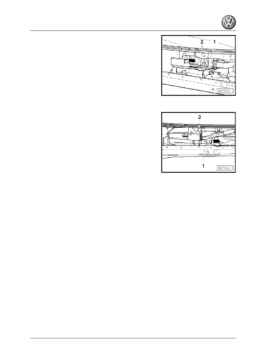
– Release front connector -1- from engine control unit and pull

it off.

– Lever up catch -2- slightly.
– Then push engine control unit out of retainer -arrow-.
– Then release rear connector on engine control unit and pull it

off.

Installing:
– Fit rear connector to engine control unit and lock in position.
– Push engine control unit onto bracket.
– Fit front connector to engine control unit and lock it in position.
– Push protective housing onto bracket.

– Tighten new shear-head bolts -1- evenly until heads shear off.
– Install plenum chamber bulkhead, plenum chamber cover and

wiper arms ⇒  Electrical system; Rep. gr.  92 ; Windscreen

wiper system; Removing and installing wiper arms .

505

6

Engine control unit - J623- (Golf, Eos,

Scirocco from 11/08; CC from 11/10)

Removing and installing engine control unit 

⇒ page 506

 .

Removing and installing engine control unit with protective hous‐

ing 

⇒ page 507

 .

6.1

Removing and installing engine control

unit

Note

If you wish to renew the engine control unit, connect the vehicle

diagnostic tester and perform the guided function “Renewing en‐

gine control unit”.

Removing
– Switch off ignition.
Golf, Eos, Scirocco:
– Remove wiper arms, plenum chamber cover and plenum

chamber bulkhead ⇒  Body; Rep. gr.  50 ; Plenum chamber

bulkhead .

Passat, CC:
– Remove wiper arms and plenum chamber cover ⇒  Body; Rep.

gr.  64 ; Assembly overview - plenum chamber cover .

All:
– Press retaining frame down in -direction of arrow- and remove

engine control unit.

– Push connector locking devices in direction of -arrow-, and pull

connectors off.

Installing

     Rep. gr.24 - Mixture preparation - injection

– Fit connectors to engine control unit and slide locking devices

onto stop in direction of -arrow-.

– Insert engine control unit into retaining frame and press re‐

taining frame upwards in -direction of arrow-

Golf, Eos, Scirocco:
– Install wiper arms, plenum chamber cover and plenum cham‐

ber bulkhead ⇒  Body; Rep. gr.  50 ; Plenum chamber bulk‐

head .

Passat, CC:
– Install wiper arms and plenum chamber cover ⇒  Body; Rep.

gr.  64 ; Assembly overview - plenum chamber cover .

6.2

Removing and installing engine control

unit with protective housing

Note

If you wish to renew the engine control unit, connect the vehi‐

cle diagnostic tester and perform the guided function “Renew‐

ing engine control unit”.

The shear-head bolt threads may coated with locking com‐

pound. To simplify removal, the shear-head bolts can be heat‐

ed using hot air blower - VAS 1978/14- . When doing this,

ensure that no adjacent cables, connectors or components are

damaged!

Removing
– Switch off ignition.
Golf, Eos, Scirocco:
– Remove wiper arms, plenum chamber cover and plenum

chamber bulkhead ⇒  Body; Rep. gr.  50 ; Plenum chamber

bulkhead .

Passat, CC:
– Remove wiper arms and plenum chamber cover ⇒  Body; Rep.

gr.  64 ; Assembly overview - plenum chamber cover .

507

All:
– Press retaining frame down in -direction of arrow- and remove

engine control unit.

– Unscrew shear-head bolts -arrows- using pliers.

– Insert screwdriver between both locking plates -arrow-.
– Carefully press screwdriver in direction of -arrow- and bend

locking bar -1- upwards at the same time.

– Bend locking bar -1- in direction of -arrow- until it can be pulled

off connector.

     Rep. gr.24 - Mixture preparation - injection

– Push connector locking devices in direction of -arrow-, and pull

connectors off.

Installing

– Fit connectors to engine control unit and slide locking devices

onto stop in direction of -arrow-.

– Fit locking bar -1- onto connectors and press it in direction of

-arrow-.

– Guide pin -2- to stop into hole on engine control unit.

– Secure retaining bow with shear-head bolts to engine control

unit -arrows-.

– Tighten shear-head bolts evenly until heads shear-head off

-arrows-.

509

– Insert engine control unit into retaining frame and press re‐

taining frame upwards in -direction of arrow-

Golf, Eos, Scirocco:
– Install wiper arms, plenum chamber cover and plenum cham‐

ber bulkhead ⇒  Body; Rep. gr.  50 ; Plenum chamber bulk‐

head .

Passat, CC:
– Install wiper arms and plenum chamber cover ⇒  Body; Rep.

gr.  64 ; Assembly overview - plenum chamber cover .

     Rep. gr.24 - Mixture preparation - injection

7

Engine control unit - J623- (Tiguan)

Removing and installing engine control unit 

⇒ page 511

 .

Removing and installing engine control unit with protective hous‐

ing 

⇒ page 512

 .

7.1

Removing and installing engine control

unit

If you wish to renew the engine control unit, connect the vehicle

diagnostic tester and perform the guided function “Renewing con‐

trol unit”.
Removing
– Switch off ignition.
– Remove wiper arms ⇒  Electrical system; Rep. gr.  92 ; Wind‐

screen wiper system; Removing and installing wiper arms .

– Remove plenum chamber cover ⇒  General body repairs, ex‐

terior; Rep. gr.  64 ; Removing and installing plenum chamber

cover.

– Pull connector -1- off heated windscreen control unit - J505- .
– Slide connector locking devices -2- on engine control unit out‐

wards and pull off both connectors.

– Remove securing bolts -3-.
– Remove retainer frame with engine control unit from plenum

chamber.

– Press locking device -1- outwards and slide engine control unit

-2- in -direction of arrow-.

511

Installing
– Slide engine control unit -1- into retaining frame in

-direction of arrow-.

– Fit retainer frame with engine control unit onto retainer -4-.
Specified torque of securing nuts for retainer -4-: 6 Nm.

– Tighten securing bolts -3- to 7 Nm.
– Fit connectors to engine control unit and slide locking devices

-2- inwards.

– Fit connector -1- to heated windscreen control unit - J505- .
– Install plenum chamber cover ⇒  General body repairs, exte‐

rior; Rep. gr.  64 ; Removing and installing plenum chamber

cover.

– Install wiper arms ⇒  Electrical system; Rep. gr.  92 ; Wind‐

screen wiper system; Removing and installing wiper arms.

7.2

Removing and installing engine control

unit with protective housing

If you wish to renew the engine control unit, connect the vehicle

diagnostic tester and perform the guided function “Renewing con‐

trol unit”.
Special tools and workshop equipment required
♦ Grip pliers
Removing
– Switch off ignition.
– Remove wiper arms, ⇒  Electrical system; Rep. gr.  92 ; Wind‐

screen wiper system; Removing and installing wiper arms.

– Remove plenum chamber cover ⇒  General body repairs, ex‐

terior; Rep. gr.  64 ; Removing and installing plenum chamber

cover.

– Unscrew bolts -1-.
– Cover the plenum chamber with a clean cloth so that it is not

scratched.

– Raise engine control unit with retaining frame slightly.
– Release engine control unit in direction of -arrow- and pull out

slightly.

     Rep. gr.24 - Mixture preparation - injection

– Bend the upper ends -1- of locking clip outwards.
– Remove shear-head bolts -2- using grip pliers and remove

locking clip.

– Slide connector locking devices -1- on engine control unit out‐

wards and pull off both connectors.

– Remove engine control unit.

Installing:
– Slide engine control unit -1- in direction of -arrow- in retaining

frame until it engages.

– Tighten the retaining frame.

Specified torque: 6 Nm

– Fit connectors to engine control unit and slide locking devices

-1- inwards.

– Take a new locking clip and tighten new shear-head bolts

evenly until heads shear off.

513

8

Engine control unit - J623- (Scirocco

to 11/08)

Removing and installing engine control unit 

⇒ page 514

 .

Removing and installing engine control unit with protective hous‐

ing 

⇒ page 515

 .

8.1

Removing and installing engine control

unit

If you wish to renew the engine control unit, connect the vehicle

diagnostic tester and perform the guided function “Renewing con‐

trol unit”.
Removing
– Switch off ignition.
– Remove wiper arms, ⇒  Electrical system; Rep. gr.  92 ; Wind‐

screen wiper system; Removing and installing wiper arms.

– Remove plenum chamber bulkhead ⇒  General body repairs;

Rep. gr.  50 ; Body - front; Plenum chamber bulkhead .

– Press retaining frame down in -direction of arrow- and remove

engine control unit.

– Push connector locking devices in direction of -arrow-, and pull

connectors off.

Installing

– Fit connectors to engine control unit and slide locking devices

onto stop in direction of -arrow-.

     Rep. gr.24 - Mixture preparation - injection

– Insert engine control unit into retaining frame and press re‐

taining frame upwards in -direction of arrow-

– Install plenum chamber bulkhead ⇒  General body repairs;

Rep. gr.  50 ; Body - front; Plenum chamber bulkhead .

– Install wiper arms ⇒  Electrical system; Rep. gr.  92 ; Wind‐

screen wiper system; Removing and installing wiper arms.

8.2

Removing and installing engine control

unit with protective housing

If you wish to renew the engine control unit, connect the vehicle

diagnostic tester and perform the guided function “Renewing con‐

trol unit”.
Removing
– Switch off ignition.
– Remove wiper arms, ⇒  Electrical system; Rep. gr.  92 ; Wind‐

screen wiper system; Removing and installing wiper arms.

– Remove plenum chamber bulkhead ⇒  General body repairs;

Rep. gr.  50 ; Body - front; Plenum chamber bulkhead .

– Press retaining frame down in -direction of arrow- and remove

engine control unit.

– Remove shear-head bolts -arrows- using pliers and remove

locking clips.

515

– Push connector locking devices in direction of -arrow-, and pull

connectors off.

Installing

– Fit connectors to engine control unit and slide locking devices

onto stop in direction of -arrow-.

– Fit the two locking clips over the connector and secure with

new shear-head bolts -arrows-.

– Tighten shear-head bolts evenly until heads shear-head off

-arrows-.

– Insert engine control unit into retaining frame and press re‐

taining frame upwards in -direction of arrow-

– Install plenum chamber bulkhead ⇒  General body repairs;

Rep. gr.  50 ; Body - front; Plenum chamber bulkhead .

– Install wiper arms ⇒  Electrical system; Rep. gr.  92 ; Wind‐

screen wiper system; Removing and installing wiper arms.

     Rep. gr.24 - Mixture preparation - injection

26 – Exhaust system

1

Exhaust system (Passat, CC)

Note

Do not bend the flexible joint in the front exhaust pipe by more

than 10° because it might otherwise be damaged.

Renew seals, gaskets and self-locking nuts.

After working on the exhaust system, ensure that the system

is not under stress and that there is sufficient clearance to the

bodywork. If necessary, loosen clamp and align silencers and

exhaust pipe so that sufficient clearance is maintained to the

bodywork at all points and the mountings are evenly loaded.

The exhaust manifold and the turbocharger are one compo‐

nent, removing and installing 

⇒ page 432

 .

Assembly overview - exhaust system (engine codes BZB, CAWA,

CAWB, CGYA) 

⇒ page 517

 .

Assembly overview - exhaust system (engine codes CCTA,

CCTB, CCZA, CDAA, CDAB) 

⇒ page 519

 .

Assembly overview - exhaust system (engine code CBFA)

⇒ page 521

 .

Separating centre and rear silencers 

⇒ page 522

 .

Align exhaust system free of stress 

⇒ page 524

 .

Mounting position and specified torque of the clamping sleeve

⇒ page 525

Removing and installing catalytic converters with front exhaust

pipe 

⇒ page 526

 .

Checking exhaust system for leaks 

⇒ page 528

 .

1.1

Assembly overview - exhaust system (engine codes BZB, CAWA, CAWB,

CGYA)

517

1 - 25 Nm
2 - Mounting

❑ Renew if damaged

3 - Seal

❑ Renew

4 - 40 Nm

❑ Renew
❑ Coat studs of exhaust

manifold with high-tem‐

perature paste.

❑ High-temperature paste

- G 052 112 A3-

5 - Front exhaust pipe with cat‐

alytic converters

Caution

Risk of damage to flexi‐

ble joint.

Do not allow the flexible

joint to kink by more than

10°.

Install flexible joint so that

it is not under tension.

Do not damage wire

mesh on decoupling ele‐

ment.

❑ Protect catalytic con‐

verter from damage by

knocks and impact

❑ Removing and installing

⇒ page 526

❑ Aligning exhaust sys‐

tem free of tension 

⇒ page 524

 .

6 - Lambda probe - G39-

❑ Bank 1, probe 1
❑ 55 Nm
❑ The thread on new Lambda probes is coated with high-temperature paste.
❑ When re-using the old Lambda probe, coat only the thread with high-temperature paste; the paste must

not get into the slots of the probe body.

❑ High-temperature paste - G 052 112 A3-

7 - Retainer

❑ Renew if damaged

8 - Mounting

❑ Renew if damaged

9 - Rear silencer

❑ In initial equipment, component with centre silencer. Can be renewed individually for repair purposes.
❑ Separate exhaust system 

⇒ page 522

10 - Threaded union

❑ Tighten bolted connections evenly. Specified torque and installation position 

⇒ page 525

11 - Rear clamp

❑ For separate replacement of centre and rear silencers

     Rep. gr.26 - Exhaust system

❑ Tighten bolted connections evenly. Specified torque and installation position 

⇒ page 525

12 - Centre silencer

❑ Combined in one unit with rear silencer as original equipment. Can be renewed individually for repair

purposes.

❑ Separate exhaust system 

⇒ page 522

13 - Threaded union

❑ Tighten bolted connections evenly. Specified torque and installation position 

⇒ page 525

14 - Front clamp

❑ Tighten bolted connections evenly. Specified torque and installation position 

⇒ page 525

15 - Mounting

❑ For centre silencer

1.2

Assembly overview - exhaust system (engine codes CCTA, CCTB, CCZA,

CDAA, CDAB)

1 - 25 Nm
2 - Mounting

❑ Renew if damaged

3 - Seal

❑ Renew

4 - 40 Nm

❑ Renew
❑ Coat studs of exhaust

manifold with high-tem‐

perature paste.

❑ High-temperature paste

- G 052 112 A3-

5 - Lambda probe - G39-

❑ Bank 1, probe 1
❑ 55 Nm
❑ The thread on new

Lambda probes is coat‐

ed with high-tempera‐

ture paste.

❑ When re-using the old

Lambda probe, coat on‐

ly the thread with high-

temperature paste; the

paste must not get into

the slots of the probe

body.

❑ High-temperature paste

- G 052 112 A3-

519

6 - Front exhaust pipe with catalytic converters

Caution

Risk of damage to flexi‐

ble joint.

Do not allow the flexible

joint to kink by more than

10°.

Install flexible joint so that

it is not under tension.

Do not damage wire

mesh on decoupling ele‐

ment.

❑ Protect catalytic converter from damage by knocks and impact
❑ Removing and installing 

⇒ page 526

❑ Aligning exhaust system free of tension 

⇒ page 524

 .

7 - Lambda probe after catalytic converter - G130-

❑ Bank 1, probe 2
❑ 55 Nm
❑ The thread on new Lambda probes is coated with high-temperature paste.
❑ When re-using the old Lambda probe, coat only the thread with high-temperature paste; the paste must

not get into the slots of the probe body.

❑ High-temperature paste - G 052 112 A3-

8 - Retainer

❑ Renew if damaged

9 - Mounting

❑ Renew if damaged

10 - Rear silencer

❑ In initial equipment, component with centre silencer. Can be renewed individually for repair purposes.
❑ Separate exhaust system 

⇒ page 522

11 - Threaded union

❑ Tighten bolted connections evenly. Specified torque and installation position 

⇒ page 525

12 - Rear clamp

❑ For separate replacement of centre and rear silencers
❑ Tighten bolted connections evenly. Specified torque and installation position 

⇒ page 525

13 - Centre silencer

❑ Combined in one unit with rear silencer as original equipment. Can be renewed individually for repair

purposes.

❑ Separate exhaust system 

⇒ page 522

14 - Threaded union

❑ Tighten bolted connections evenly. Specified torque and installation position 

⇒ page 525

15 - Front clamp

❑ Tighten bolted connections evenly. Specified torque and installation position 

⇒ page 525

16 - Mounting

❑ For centre silencer

     Rep. gr.26 - Exhaust system

1.3

Assembly overview - exhaust system (engine code CBFA)

1 - 25 Nm
2 - Mounting

❑ Renew if damaged

3 - Seal

❑ Renew

4 - 40 Nm

❑ Renew
❑ Coat studs of exhaust

manifold with high-tem‐

perature paste.

❑ High-temperature paste

- G 052 112 A3-

5 - Lambda probe - G39-

❑ Bank 1, probe 1
❑ 55 Nm
❑ The thread on new

Lambda probes is coat‐

ed with high-tempera‐

ture paste.

❑ When re-using the old

Lambda probe, coat on‐

ly the thread with high-

temperature paste; the

paste must not get into

the slots of the probe

body.

❑ High-temperature paste

- G 052 112 A3-

6 - Front exhaust pipe with cat‐

alytic converters

Caution

Risk of damage to flexi‐

ble joint.

Do not allow the flexible

joint to kink by more than

10°.

Install flexible joint so that

it is not under tension.

Do not damage wire

mesh on decoupling ele‐

ment.

❑ Protect catalytic converter from damage by knocks and impact
❑ Removing and installing 

⇒ page 526

❑ Aligning exhaust system free of tension 

⇒ page 524

 .

7 - Lambda probe 2 - G108-

❑ Bank 1, probe 2
❑ 55 Nm
❑ The thread on new Lambda probes is coated with high-temperature paste.
❑ When re-using the old Lambda probe, coat only the thread with high-temperature paste; the paste must

not get into the slots of the probe body.

521

❑ High-temperature paste - G 052 112 A3-

8 - Lambda probe after catalytic converter - G130-

❑ Bank 1, probe 3
❑ 55 Nm
❑ The thread on new Lambda probes is coated with high-temperature paste.
❑ When re-using the old Lambda probe, coat only the thread with high-temperature paste; the paste must

not get into the slots of the probe body.

❑ High-temperature paste - G 052 112 A3-

9 - Retainer

❑ Renew if damaged

10 - Mounting

❑ Renew if damaged

11 - Rear silencer

❑ In initial equipment, component with centre silencer. Can be renewed individually for repair purposes.
❑ Separate exhaust system 

⇒ page 522

12 - Threaded union

❑ Tighten bolted connections evenly. Specified torque and installation position 

⇒ page 525

13 - Rear clamp

❑ For separate replacement of centre and rear silencers
❑ Tighten bolted connections evenly. Specified torque and installation position 

⇒ page 525

14 - Centre silencer

❑ Combined in one unit with rear silencer as original equipment. Can be renewed individually for repair

purposes.

❑ Separate exhaust system 

⇒ page 522

15 - Threaded union

❑ Tighten bolted connections evenly. Specified torque and installation position 

⇒ page 525

16 - Front clamp

❑ Tighten bolted connections evenly. Specified torque and installation position 

⇒ page 525

17 - Mounting

❑ For centre silencer

1.4

Separating centre and rear silencers

Note

The connecting pipe can be cut through at the cutting location

in order to remove and install or renew the centre and rear

silencers separately.

Cutting location is marked by an indentation on the circumfer‐

ence of exhaust pipe.

Special tools and workshop equipment required

     Rep. gr.26 - Exhaust system

♦ Pneumatic sabre saw - V.A.G 1523 A-

Or
♦ Chain-type pipe cutter - VAS 6254-

WARNING

To avoid injury from metal shavings, wear eye protection and

protective clothing.

– Cut through exhaust pipe at right angles using e.g. body saw

- V.A.G 1523 A- at separating point -arrow-.

– Position clamping sleeve between side markings when instal‐

ling.

– Install clamp so that ends of bolts do not protrude beyond bot‐

tom of clamp.

523

– Align exhaust system so that the distance -a- on left and right

is even.

Specified torque:

Clamp with 2 individual clips: 25 Nm
Clamp with continuous clip: 35 Nm

1.5

Aligning exhaust system free of stress

• The exhaust system must be aligned when cold.
– Loosen bolts -3 and 4- on front clamp -1-.
– Align front clamp -1- to marking -A- on front exhaust pipe -2-

(-arrow- points forwards).

• Dimension -a- = 

⇒ page 525

• Do not allow the bolts must be on the right and the ends to

protrude beyond the lower edge of the clamp.

– Tighten front clamp bolts -3- hand-tight.

– Push exhaust system forward until preload on rubber mount‐

ing for rear silencer is dimension -a- 15…17 mm.

– In this position, tighten bolts -3 and 4- of front clamp evenly.

Specified torque 

⇒ page 525

 .

     Rep. gr.26 - Exhaust system

1.6

Installation position and specified torque

of clamp

Note

Gradual introduction of clamp with continuous clip.

Specified torque and installation dimensions of clamp
Clamp -A- with 2 individual clips.

Specified torque: 25 Nm
Installation dimensions -a- 5 mm (only for front clamp)

Clamp -B- with continuous clip.

Specified torque: 35 Nm
Installation dimensions -a- 8.5 mm (only for front clamp)

Installation dimension -a- for vehicles with marking on front ex‐

haust pipe
1 - Clamping sleeve
2 - Front exhaust pipe
a - Installation dimension
A - Marking

Installation position of front clamp
– Install clamp so that end of bolt -arrow- does not extend be‐

yond lower edge of clamp.

• Threaded connection faces right

525

Installation position of rear clamp
– Install clamp so that end of bolt -arrow- does not extend be‐

yond lower edge of clamp.

• Threaded connection faces to rear.

1.7

Removing and installing catalytic con‐

verters with front exhaust pipe

Removing:
– Remove air filter 

⇒ page 467

 .

Engine codes CBFA, CCTA, CCTB, CDAA, CDAB:
– Disconnect connector for Lambda probe - G39- -arrow- and

lay cable to side.

All:
– Remove nuts (accessible from above) -arrows- securing front

exhaust pipe to turbocharger.

– Unscrew nuts (accessible from below) securing front exhaust

pipe to turbocharger.

– Unscrew nuts -arrows- and pull underbody cover down slight‐

ly.

     Rep. gr.26 - Exhaust system

Engine codes BZB, CAWA, CAWB, CCTA, CCTB, CGYA:
– Separate electrical connection -arrow- on right of underbody.
– Remove electrical connector from bracket and lay electrical

line to Lambda probe to side.

Engine code CBFA:
– Unclip lines -arrows-, pull off retainer -2- and separate con‐

nectors -1 and 3-.

All:
– Unbolt bracket for exhaust system -arrows-.

527

– Remove cross member for underbody -arrows-.

Caution

Danger of damage to the de-coupling elements.

♦ Do not bend de-coupling elements in front exhaust pipe

by more than 10°.

– Loosen clamp -1- and push to rear.
– Remove catalytic converters with front exhaust pipe.
Installing:
Installation is carried out in the reverse order. When installing,

note the following:
♦ Coat studs of turbocharger with high-temperature paste - G

052 112 A3- .

♦ Renew seals, gaskets and self-locking nuts.
♦ Align exhaust system free of stress 

⇒ page 524

 .

Specified torques

⇒ “1.1 Assembly overview - exhaust system (engine codes BZB,

CAWA, CAWB, CGYA)”, page 517
⇒ “1.2 Assembly overview - exhaust system (engine codes CCTA,

CCTB, CCZA, CDAA, CDAB)”, page 519
⇒ “1.3 Assembly overview - exhaust system (engine code

CBFA)”, page 521

Component


Nm

Tunnel cross-piece to body


25

1.8

Check exhaust system for leaks

Proceed as follows:
– Start engine and allow to idle.
– Seal exhaust tailpipe briefly (e.g. hold cloth over end).
– Check for leaks and listen for noise at connecting points (cyl‐

inder head/exhaust manifold, exhaust manifold/front exhaust

pipe, etc.) with the assistance of a 2nd mechanic.

– Repair any leaks found.

     Rep. gr.26 - Exhaust system

2

Exhaust system (Golf, Eos, Scirocco)

Note

Do not bend the flexible joint in the front exhaust pipe by more

than 10° because it might otherwise be damaged.

Renew seals, gaskets and self-locking nuts.

After working on the exhaust system, ensure that the system

is not under stress and that there is sufficient clearance to the

bodywork. If necessary, loosen clamp and align silencers and

exhaust pipe so that sufficient clearance is maintained to the

bodywork at all points and the mountings are evenly loaded.

The exhaust manifold and the turbocharger are one compo‐

nent. Removing and installing 

⇒ page 432

 .

Assembly overview - exhaust system (engine code CAWB)

⇒ page 529

 .

Assembly overview - exhaust system (Golf 2004 ►, Eos, Scirocco,

engine codes CCTA, CCZA, CCZB) 

⇒ page 532

Assembly overview - exhaust system (engine code CBFA)

⇒ page 534

 .

Assembly overview - exhaust system (Golf 2009►, engine codes

CCZA, CCZB) 

⇒ page 536

Assembly overview - exhaust system (Golf 2009 ►, engine codes

CCTA, CDAA) 

⇒ page 538

Separating centre and rear silencers 

⇒ page 539

 .

Align exhaust system free of stress 

⇒ page 540

 .

Installation position and specified torque of clamp

⇒ page 541

 .

Removing and installing catalytic converters with front exhaust

pipe 

⇒ page 542

 .

Checking exhaust system for leaks 

⇒ page 544

 .

2.1

Assembly overview - exhaust system (engine code CAWB)

529

1 - 40 Nm

❑ Renew
❑ Coat studs of exhaust

manifold with high-tem‐

perature paste.

❑ High-temperature paste

- G 052 112 A3-

2 - Lambda probe - G39-

❑ Bank 1, probe 1
❑ 55 Nm
❑ The thread on new

Lambda probes is coat‐

ed with high-tempera‐

ture paste.

❑ When re-using the old

Lambda probe, coat on‐

ly the thread with high-

temperature paste; the

paste must not get into

the slots of the probe

body.

❑ High-temperature paste

- G 052 112 A3-

3 - Front exhaust pipe with cat‐

alytic converters

Caution

Risk of damage to flexi‐

ble joint.

Do not allow the flexible

joint to kink by more than

10°.

Install flexible joint so that

it is not under tension.

Do not damage wire

mesh on decoupling ele‐

ment.

❑ Protect catalytic converter from damage by knocks and impact
❑ Removing and installing 

⇒ page 542

❑ Aligning exhaust system free of tension 

⇒ page 540

 .

4 - Retainer

❑ Renew if damaged

5 - Threaded union

❑ Tighten bolted connections evenly. Specified torque and installation position 

⇒ page 541

6 - Rear silencer

❑ In initial equipment, component with centre silencer. Can be renewed individually for repair purposes.
❑ Separate exhaust system 

⇒ page 539

7 - Mounting

❑ Renew if damaged

8 - 25 Nm
9 - Rear clamp

❑ For separate replacement of centre and rear silencers
❑ Tighten bolted connections evenly. Specified torque and installation position 

⇒ page 541

     Rep. gr.26 - Exhaust system

10 - Centre silencer

❑ Combined in one unit with rear silencer as original equipment. Can be renewed individually for repair

purposes.

❑ Separate exhaust system 

⇒ page 539

11 - 25 Nm
12 - Front clamp

❑ Tighten bolted connections evenly. Specified torque and installation position 

⇒ page 541

❑ Tighten bolted connections evenly.

13 - Threaded union

❑ Tighten bolted connections evenly. Specified torque and installation position 

⇒ page 541

14 - Mounting

❑ For centre silencer

15 - Mounting

❑ Renew if damaged

16 - Seal

❑ Renew

531

2.2

Assembly overview - exhaust system (Golf 2004 ►, Eos, Scirocco, engine

codes CCTA, CCZA, CCZB)

1 - 40 Nm

❑ Renew
❑ Coat studs of exhaust

manifold with high-tem‐

perature paste.

❑ High-temperature paste

- G 052 112 A3-

2 - Front exhaust pipe with cat‐

alytic converters

Caution

Risk of damage to flexi‐

ble joint.

Do not allow the flexible

joint to kink by more than

10°.

Install flexible joint so that

it is not under tension.

Do not damage wire

mesh on decoupling ele‐

ment.

❑ Protect catalytic con‐

verter from damage by

knocks and impact

❑ Removing and installing

⇒ page 542

❑ Aligning exhaust sys‐

tem free of tension

⇒ page 540

 .

3 - Lambda probe after catalyt‐

ic converter - G130-

❑ Bank 1, probe 2
❑ 55 Nm
❑ The thread on new Lambda probes is coated with high-temperature paste.
❑ When re-using the old Lambda probe, coat only the thread with high-temperature paste; the paste must

not get into the slots of the probe body.

❑ High-temperature paste - G 052 112 A3-

4 - Retainer

❑ Renew if damaged

5 - Nut

❑ Tighten bolted connections evenly. Specified torque and installation position 

⇒ page 541

6 - Rear silencer

❑ In initial equipment, component with centre silencer. Can be renewed individually for repair purposes.
❑ Separate exhaust system 

⇒ page 539

7 - Mounting

❑ Renew if damaged

     Rep. gr.26 - Exhaust system

8 - 25 Nm
9 - Rear clamp

❑ For separate replacement of centre and rear silencers
❑ Tighten bolted connections evenly. Specified torque and installation position 

⇒ page 541

10 - Centre silencer

❑ Combined in one unit with rear silencer as original equipment. Can be renewed individually for repair

purposes.

❑ Separate exhaust system 

⇒ page 539

11 - 25 Nm
12 - Front clamp

❑ Tighten bolted connections evenly. Specified torque and installation position 

⇒ page 541

13 - Nut

❑ Tighten bolted connections evenly. Specified torque and installation position 

⇒ page 541

14 - Mounting

❑ For centre silencer

15 - Mounting

❑ Renew if damaged

16 - Seal

❑ Renew

17 - Lambda probe - G39-

❑ Bank 1, probe 1
❑ 55 Nm
❑ The thread on new Lambda probes is coated with high-temperature paste.
❑ When re-using the old Lambda probe, coat only the thread with high-temperature paste; the paste must

not get into the slots of the probe body.

❑ High-temperature paste - G 052 112 A3-

533

2.3

Assembly overview - exhaust system (engine code CBFA)

1 - 40 Nm

❑ Renew
❑ Coat studs of exhaust

manifold with high-tem‐

perature paste.

❑ High-temperature paste

- G 052 112 A3-

2 - Lambda probe 2 - G108-

❑ Bank 1, probe 2
❑ 55 Nm
❑ The thread on new

Lambda probes is coat‐

ed with high-tempera‐

ture paste.

❑ When re-using the old

Lambda probe, coat on‐

ly the thread with high-

temperature paste; the

paste must not get into

the slots of the probe

body.

❑ High-temperature paste

- G 052 112 A3-

3 - Front exhaust pipe with cat‐

alytic converters

Caution

Risk of damage to flexi‐

ble joint.

Do not allow the flexible

joint to kink by more than

10°.

Install flexible joint so that

it is not under tension.

Do not damage wire

mesh on decoupling ele‐

ment.

❑ Protect catalytic converter from damage by knocks and impact
❑ Removing and installing 

⇒ page 542

❑ Aligning exhaust system free of tension 

⇒ page 540

 .

4 - Lambda probe after catalytic converter - G130-

❑ Bank 1, probe 3
❑ 55 Nm
❑ The thread on new Lambda probes is coated with high-temperature paste.
❑ When re-using the old Lambda probe, coat only the thread with high-temperature paste; the paste must

not get into the slots of the probe body.

❑ High-temperature paste - G 052 112 A3-

5 - Retainer

❑ Renew if damaged

6 - Nut

❑ Tighten bolted connections evenly. Specified torque and installation position 

⇒ page 541

     Rep. gr.26 - Exhaust system

7 - Rear silencer

❑ In initial equipment, component with centre silencer. Can be renewed individually for repair purposes.
❑ Separate exhaust system 

⇒ page 539

8 - Mounting

❑ Renew if damaged

9 - 25 Nm
10 - Rear clamp

❑ For separate replacement of centre and rear silencers
❑ Tighten bolted connections evenly. Specified torque and installation position 

⇒ page 541

11 - Centre silencer

❑ Combined in one unit with rear silencer as original equipment. Can be renewed individually for repair

purposes.

❑ Separate exhaust system 

⇒ page 539

12 - 25 Nm
13 - Front clamp

❑ Tighten bolted connections evenly. Specified torque and installation position 

⇒ page 541

14 - Nut

❑ Tighten bolted connections evenly. Specified torque and installation position 

⇒ page 541

15 - Mounting

❑ For centre silencer

16 - Mounting

❑ Renew if damaged

17 - Seal

❑ Renew

18 - Lambda probe - G39-

❑ Bank 1, probe 1
❑ 55 Nm
❑ The thread on new Lambda probes is coated with high-temperature paste.
❑ When re-using the old Lambda probe, coat only the thread with high-temperature paste; the paste must

not get into the slots of the probe body.

❑ High-temperature paste - G 052 112 A3-

535

2.4

Assembly overview - exhaust system (Golf 2009►, engine codes CCZA,

CCZB)

1 - 40 Nm

❑ Renew
❑ Coat studs of exhaust

manifold with high-tem‐

perature paste.

❑ High-temperature paste

- G 052 112 A3-

2 - Lambda probe - G39-

❑ Bank 1, probe 1
❑ 55 Nm
❑ The thread on new

Lambda probes is coat‐

ed with high-tempera‐

ture paste.

❑ When re-using the old

Lambda probe, coat on‐

ly the thread with high-

temperature paste; the

paste must not get into

the slots of the probe

body.

❑ High-temperature paste

- G 052 112 A3-

3 - Front exhaust pipe with cat‐

alytic converters

Caution

Risk of damage to flexi‐

ble joint.

Do not allow the flexible

joint to kink by more than

10°.

Install flexible joint so that

it is not under tension.

Do not damage wire

mesh on decoupling ele‐

ment.

❑ Protect catalytic converter from damage by knocks and impact
❑ Removing and installing 

⇒ page 542

❑ Aligning exhaust system free of tension 

⇒ page 540

 .

4 - Lambda probe after catalytic converter - G130-

❑ Bank 1, probe 2
❑ 55 Nm
❑ The thread on new Lambda probes is coated with high-temperature paste.
❑ When re-using the old Lambda probe, coat only the thread with high-temperature paste; the paste must

not get into the slots of the probe body.

❑ High-temperature paste - G 052 112 A3-

5 - Retainer

❑ Renew if damaged

     Rep. gr.26 - Exhaust system


Content      ..     15      16      17      18     ..