Volkswagen 4-cyl. injection engine (1.8 and 2.0 l engine, chain drive). Manual (Edition 08.2018) - page 15
 

  Index      Manuals     Volkswagen 4-cyl. injection engine (1.8 and 2.0 l engine, chain drive). Manual (Edition 08.2018). Workshop Manual (Edition 08.2018)


Search            copyright infringement  


Content      ..     13      14      15      16     ..


Volkswagen 4-cyl. injection engine (1.8 and 2.0 l engine, chain drive). Manual (Edition 08.2018) - page 15


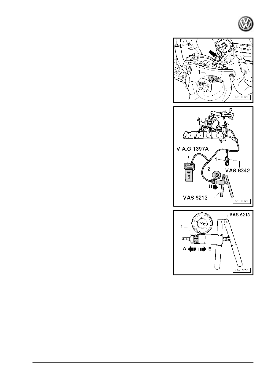
– Pre-adjust bypass flap -1- above rod of vacuum unit -arrow-,

so that the bypass flap can just be turned by hand.

– Tighten lock nut hand-tight.

– Connect up hand-operated vacuum pump - VAS 6213- , tur‐

bocharger tester - V.A.G 1397A- (connection II) and pressure

control valve - VAS 6342- as shown in illustration.

– Close pressure control valve - VAS 6342- at lever -1-.

– Move slide ring -1- on hand vacuum pump - VAS 6213- to po‐

sition -B- for “pressure”.

– Switch on turbocharger tester - V.A.G 1397A- and set sliding

switch to position II.

441

– Secure universal dial gauge bracket - VW 387- to turbocharger

-arrows-.

– Secure dial gauge - VAS 6341/1- with dial gauge extension,

30 mm - VAS 6341/3- and flat pickup - VAS 6341/4- to uni‐

versal dial gauge bracket - VW 387- .

– With pressure at 0 bar, set dial gauge - VAS 6341/1- to 1 mm

preload.

– Turn dial of dial gauge - VAS 6341/1- to 0.
– Make sure that dial gauge can move freely.
– Operate hand vacuum pump - VAS 6213- until turbocharger

tester - V.A.G 1397A- indicates 460 +/- 5 mbar.

– The dial gauge must indicate between 4.1 mm and 4.3 mm;

otherwise, turn rod of vacuum unit until the value is indicated.

– Tighten lock nut hand-tight.
– Repeat adjustment.

Note

The values in mm refer to the read value (includes 1 mm preten‐

sion).

– Vent system via pressure control valve - VAS 6342- so that

pressure reading drops to 0 mbar.

– Set dial gauge - VAS 6341/1- to 0.

Note

The following measurements must be performed in continuous

sequence. Do not allow the pressure to drop to 0 between meas‐

urements.

– Operate hand vacuum pump - VAS 6213- until turbocharger

tester - V.A.G 1397A- indicates 460 +/- 5 mbar.

– Read off and note value indicated on dial gauge - VAS

6341/1- .

– Actuate hand vacuum pump - VAS 6213- until turbocharger

tester - V.A.G 1397A- indicates 650 mbar to 700 mbar.

– Vent system via pressure control valve - VAS 6342- so that

pressure reading drops to 460 +/- 5 mbar.

– Read off and note value indicated on dial gauge - VAS

6341/1- .

– Add values 1 and 2 together and divide by 2.
– The result (mean value) should be 5 +/- 0.25 mm.
– Correct setting if the result (average) is not 5 +/- 0.25 mm,

tighten lock nut hand-tight and repeat measurement.

– If the result (mean value) is 5 +/- -0.25 mm, tighten the lock

nut to 9 Nm and secure with sealing paint.

     Rep. gr.21 - Turbocharging/supercharging

– Secure locking plate -1- above linkage on turbocharger.

1.6

Removing and installing vacuum unit for

turbocharger

Removing:
– Remove turbocharger 

⇒ page 432

 .

Engine code BZB, CGYA, CDAA, CDAB:
– Detach locking plate above turbocharger linkage.
– Loosen lock nut -2-.
– Separate rod from turbocharger -3-.
– Remove vacuum unit -1- from turbocharger -arrows-.

Engine codes CAWA, CAWB, CBFA, CCTA, CCTB, CCZA,

CCZB, CCZC, CCZD:
– Pull securing clip off vacuum unit linkage.

443

– Remove vacuum unit -1- from turbocharger -arrows-.
Installing:
Installation is carried out in the reverse order. When installing,

note the following:
Engine code BZB, CGYA, CDAA, CDAB:
– Adjust vacuum unit 

⇒ page 439

 .

Specified torques

Component


Nm

Vacuum unit to turbocharger

10

     Rep. gr.21 - Turbocharging/supercharging

2

Charge air system

Caution

The screw-type clips on the charge air pipes must be tightened

to 5.5 Nm. If the torque is too low or too high, the charge air

hose may slip off the charge air pipe during vehicle operation.

Installing hose connections with plug-in connectors 

⇒ page 431

 .

Assembly overview - charge air cooling (Passat, CC, Tiguan, Eos)

⇒ page 445

 .

Assembly overview - charge air cooler (Golf, Scirocco)

⇒ page 446

 .

Assembly overview - sound generator (Golf, Scirocco)

⇒ page 448

 .

Actuator for structure-borne sound - R214- and control unit for

structure-borne sound - J869- (Golf, Scirocco) 

⇒ page 448

 .

Turbocharging - overview 

⇒ page 451

 .

Removing and installing charge air cooler (Golf, Eos)

⇒ page 451

 .

Removing and installing charge air cooler (Passat, CC, Scirocco)

⇒ page 453

 .

Removing and installing charge air cooler (Tiguan) 

⇒ page 454

 .

Removing and installing charge air duct to sound generator (Golf,

Scirocco) 

⇒ page 455

 .

Checking charge air system for leaks 

⇒ page 456

 .

2.1

Assembly overview - charge air cooling

(Passat, CC, Tiguan, Eos)

Caution

The screw-type clips on the charge air pipes must be tightened

to 5.5 Nm. If the torque is too low or too high, the charge air

hose may slip off the charge air pipe during vehicle operation.

445

1 - 5 Nm
2 - Mountings

❑ For charge air cooler.

3 - Charge air cooler

❑ Removing and installing

(Passat, CC, Eos)

⇒ page 453

 .

❑ Removing and installing

(Tiguan) 

⇒ page 454

4 - Charge air pipe
5 - 10 Nm
6 - From turbocharger
7 - Charge air hose

❑ Note installation instruc‐

tions 

⇒ page 431

8 - To throttle valve module -

J338- .
9 - Charge air hose
10 - 10 Nm
11 - 5 Nm
12 - Charge air pressure send‐

er - G31-
13 - Charge air pipe
14 - Charge air hose

❑ Note installation instruc‐

tions 

⇒ page 431

2.2

Assembly overview - charge air cooler

(Golf, Scirocco)

Caution

The screw-type clips on the charge air pipes must be tightened

to 5.5 Nm. If the torque is too low or too high, the charge air

hose may slip off the charge air pipe during vehicle operation.

Note

The sound generator is not fitted on all vehicles.

     Rep. gr.21 - Turbocharging/supercharging

1 - 5 Nm
2 - Mountings

❑ For charge air cooler.

3 - Charge air cooler

❑ Removing and installing

⇒ page 453

4 - Charge air pipe
5 - 10 Nm
6 - Charge air hose

❑ Fitting hose connec‐

tions with plug-in con‐

nectors 

⇒ page 431

7 - Charge air pipe

❑ To sound generator
❑ Removing and installing

⇒ page 455

8 - Charge air hose

❑ Removing and installing

⇒ page 455

❑ Fitting hose connec‐

tions with plug-in con‐

nectors 

⇒ page 431

9 - Hose clamp
10 - Charge air hose

❑ To throttle valve module

- J338- .

11 - Charge air hose
12 - Charge air pipe

❑ Assembly overview

⇒ page 448

13 - Charge air hose

❑ Assembly overview 

⇒ page 448

14 - 8 Nm
15 - Sound generator

❑ Assembly overview 

⇒ page 448

16 - Charge air pipe
17 - Charge air hose

❑ Fitting hose connections with plug-in connectors 

⇒ page 431

18 - Charge air pressure sender - G31-
19 - 5 Nm

447

2.3

Assembly overview - sound generator

(Golf, Scirocco)

Note

The sound generator is not fitted on all vehicles. As of 04/2009,

the sound generator will be gradually replaced by the actuator for

structure-borne sound - R214- .

1 - Cover
2 - 8 Nm
3 - Plenum chamber bulkhead
4 - Trim

❑ For feed-through in ple‐

num chamber bulkhead

5 - Charge air pipe
6 - Clip
7 - Charge air hose
8 - 8 Nm
9 - Spacer sleeve
10 - Rubber mounting
11 - Sound generator

❑ Before removing, re‐

move cover

⇒ Item 1 (page 448)

 .

12 - Bracket

❑ For sound generator

13 - 8 Nm

2.4

Actuator for structure-borne sound -

R214- and control unit for structure-

borne sound - J869-

Note

Actuator for structure-borne sound - R214- and control unit for

structure-borne sound - J869- are not fitted in all vehicles!

     Rep. gr.21 - Turbocharging/supercharging

To remove and install, plenum chamber cover and plenum cham‐

ber bulkhead must be removed ⇒  Body - front; Rep. gr.  50 .
Assembly overview - actuator for structure-borne sound - R214-

and control unit for structure-borne sound - J869- (left-hand drive

vehicles) 

⇒ page 449

 .

Assembly overview - actuator for structure-borne sound - R214-

and control unit for structure-borne sound - J869- (right-hand

drive vehicles) 

⇒ page 450

 .

2.4.1

Assembly overview - actuator for structure-borne sound - R214- and control

unit for structure-borne sound - J869- (left-hand drive vehicles)

1 - Control unit for structure-

borne sound - J869-

❑ Fitting location: in ple‐

num chamber

❑ To remove and install,

plenum chamber cover

and plenum chamber

bulkhead must be re‐

moved.

2 - 8 Nm
3 - 8 Nm
4 - Bracket for actuator for

structure-borne sound - R214-

❑ Not on Scirocco.

5 - 15 Nm
6 - 8 Nm

❑ Not on Scirocco.

7 - 8 Nm
8 - Actuator for structure-borne

sound - R214-

❑ Fitting location: in ple‐

num chamber

❑ To remove and install,

plenum chamber cover

and plenum chamber

bulkhead must be re‐

moved.

9 - Bracket for control unit for

structure-borne sound - J869-
10 - 8 Nm

449

2.4.2

Assembly overview - actuator for structure-borne sound - R214- and control

unit for structure-borne sound - J869- (right-hand drive vehicles)

1 - Bracket for control unit for

structure-borne sound - J869-
2 - 8 Nm
3 - 8 Nm
4 - 15 Nm
5 - 8 Nm

❑ Not on Scirocco.

6 - Bracket for actuator for

structure-borne sound - R214-

❑ Not on Scirocco.

7 - Actuator for structure-borne

sound - R214-

❑ Fitting location: in ple‐

num chamber

❑ To remove and install,

plenum chamber cover

and plenum chamber

bulkhead must be re‐

moved.

8 - Control unit for structure-

borne sound - J869-

❑ Fitting location: in ple‐

num chamber

❑ To remove and install,

plenum chamber cover

and plenum chamber

bulkhead must be re‐

moved.

9 - 8 Nm

     Rep. gr.21 - Turbocharging/supercharging

2.5

Turbocharging - overview

1 - Brake servo
2 - Non-return valve
3 - Vacuum pump
4 - Air mass meter - G70-
5 - Air filter
6 - Pressure regulating valve

❑ For crankcase ventila‐

tion.

7 - Intake manifold flap air flow

control valve - N316-
8 - Vacuum unit for intake

manifold change-over
9 - Non-return valve

❑ Different versions, allo‐

cation ⇒  ETKA (Elec‐

tronic parts catalogue)

10 - Charge air cooler
11 - Throttle valve module -

J338-
12 - Activated charcoal filter

solenoid valve 1 - N80-
13 - To activated charcoal filter
14 - Intake manifold
15 - Non-return valve
16 - Vacuum unit for charge

pressure control
17 - Charge pressure control

solenoid valve - N75-
18 - Turbocharger air recircu‐

lation valve - N249-
19 - Exhaust turbocharger

2.6

Removing and installing charge air cool‐

er (Golf, Eos)

Removing:
– Remove noise insulation ⇒  General body repairs, exterior;

Rep. gr.  50 ; Noise insulation .

– Remove bumper cover ⇒  Bumpers; Rep. gr.  63 ; Removing

and installing front bumper cover .

– Drain coolant 

⇒ page 241

 .

451

– Remove right air hose -arrows-.
– Remove radiator cowl 

⇒ page 273

 .

– Removing radiator 

⇒ page 275

 .

Pipes of condenser are bolted to right-hand side of charge air

cooler. To unscrew securing bolts, proceed as follows:

– Make a paper template with the specified dimensions.

– Fit the template on the plastic bracket at the front right so that

it rests against the edges at the top and left.

– Mark the intersection on the template -arrow- with a centre

punch.

– Drill a hole into the plastic bracket with a 5-mm drill bit.
– Drill or cut the hole to 16 mm.

– Unscrew securing bolt -arrow- for condenser pipes.

     Rep. gr.21 - Turbocharging/supercharging

– Unscrew bolts -1- for charge air cooler mountings.

Note

The securing bolts of the condenser are difficult to access. With

the aid of a second mechanic, lift the charge air cooler out of the

radiator mountings. The charge air cooler can now be moved

»back and forth« to allow access to the securing bolts.

– Unbolt condenser from charge air cooler -arrows-.
– Attach condenser to lock carrier using cable ties.
– Take out charge air cooler from underneath.
Installing:
Installation is carried out in the reverse order. When installing,

note the following:
♦ Hose connections and hoses for charge air system must be

free of oil and grease before assembly. The seal and sealing

surface must be oiled lightly only for plug-in connectors

⇒ page 431

 .

2.7

Removing and installing charge air cool‐

er (Passat, CC, Scirocco)

Removing:
– Remove noise insulation ⇒  General body repairs, exterior;

Rep. gr.  50 ; Noise insulation .

– Remove bumper cover ⇒  Bumpers; Rep. gr.  63 ; Removing

and installing front bumper cover .

– Drain coolant 

⇒ page 241

 .

– Remove right air hose -arrows-.
– Remove radiator cowl 

⇒ page 273

 .

– Removing radiator 

⇒ page 275

 .

– Remove air deflector elements on lock carrier ⇒  Body - front;

Rep. gr.  50 ; Assembly overview - air deflector elements on

lock carrier .

453

– Unscrew bolts -1- for charge air cooler mountings.

Note

The securing bolts of the condenser are difficult to access. With

the aid of a second mechanic, lift the charge air cooler out of the

radiator mountings. The charge air cooler can now be moved

»back and forth« to allow access to the securing bolts.

– On the right-hand side of the charge air cooler unscrew pipes

of condenser -arrow-.

– Unbolt condenser from charge air cooler -arrows-.
– Attach condenser to lock carrier using cable ties.
– Take out charge air cooler from underneath.
Installing:
Installation is carried out in the reverse order. When installing,

note the following:
♦ Hose connections and hoses for charge air system must be

free of oil and grease before assembly. The seal and sealing

surface must be oiled lightly only for plug-in connectors

⇒ page 431

 .

2.8

Removing and installing charge air cool‐

er, Tiguan

– Removing radiator 

⇒ page 275

 .

– Remove bumper cover ⇒  Bumpers; Rep. gr.  63 ; Removing

and installing front bumper cover .

– Unclip air deflector parts on left and right of lock carrier ⇒ 

Body, front; Rep. gr.  50 ; Assembly overview - lock carrier .

     Rep. gr.21 - Turbocharging/supercharging

– Unscrew bolts -arrows- for charge air cooler mountings.

– Unbolt condenser from charge air cooler -arrows-.
– Secure condenser to lock carrier with cable ties.
– Remove charge air cooler downwards.
Installing:
Installation is carried out in the reverse order. When installing,

note the following:
♦ Hose connections and hoses for charge air system must be

free of oil and grease before assembly. The seal and sealing

surface must be oiled lightly only for plug-in connectors

⇒ page 431

 .

2.9

Removing and installing charge air duct

to sound generator (Golf, Scirocco)

Special tools and workshop equipment required
♦ Engine bung set - VAS 6122-

Removing:
– Pull cover off air duct (release clips on sides) -arrows-.

455

– Release clips -arrows- air duct at the bottom and remove duct.
– Detach air duct at bottom together with air hose.

– Open latch -1-, unclip fuel lines -2- and slacken bolts -3-.

– Loosen clip -arrow- and remove charge air duct.
– Seal connection for charge air duct with plug from engine bung

set - VAS 6122- .

Installing:
Install in reverse order of removal.

2.10

Checking charge air system for leaks

Special tools and workshop equipment required
♦ Charge air system tester - V.A.G 1687-

♦ Adapter - V.A.G 1687/5-
– Remove noise insulation ⇒  General body repairs, exterior;

Rep. gr.  50 ; Noise insulation .

     Rep. gr.21 - Turbocharging/supercharging

– Release clip -A- and detach hose -B- from charge air pipe.

– Fit adapter - V.A.G 1687/5- onto charge air hose -A- and turn

adapter through approx. 90° -B-.

Prepare charge air system tester - V.A.G 1687- as follows:

– Turn pressure control valve -2- anti-clockwise onto stop.
– Close valves -3- and -4-.

Note

To turn the pressure regulating valve -2- the knob must be pulled

upwards.

– Connect charge air system tester - V.A.G 1687- as shown.

457

– Connect compressed air hose -1- (compressed air source) to

charge air system tester - V.A.G 1687- .

Note

If there is water in the sight glass, drain at water drain screw -6-.

– Open valve -3-.
– Adjust pressure to 0.5 bar with pressure regulating valve -2-.

Caution

The pressure must remain at or below 0.5 bar! If the pressure

is too high this can cause damage to the engine.

– Open valve -4- and wait until the test circuit is filled. If neces‐

sary readjust pressure to 0.5 bar.

– Check the charge air system for leaks by hearing, touching,

with commercially available leak detector spray or using ultra‐

sonic tester - V.A.G 1842- .

Note

Fitting hose connections with plug-in connectors 

⇒ page 431

A small amount of air escapes through the valves and enters

the engine. Therefore a holding pressure test is not possible.

Ultrasonic tester - V.A.G 1842- ⇒  operating instructions

Depressurise test circuit by detaching coupling from adapter -

V.A.G 1687/5- before removing adapter.

Hose connections and hoses for charge air system must be

free of oil and grease before assembly.

     Rep. gr.21 - Turbocharging/supercharging

24 – Mixture preparation - injection

1

Safety precautions and rules for

cleanliness

General notes on self-diagnosis 

⇒ page 459

 .

Safety precautions 

⇒ page 278

 .

Comply with rules for cleanliness 

⇒ page 280

 .

1.1

General information on self-diagnosis

♦ The engine control unit has a self-diagnosis capability. Before

carrying out repairs and for fault finding, first read event mem‐

ory. Also the vacuum hoses and connections must be checked

(unmetered air).

♦ Fuel hoses in engine compartment must be secured only with

spring-type clips. The use of crimp-type or screw-type clips is

not permissible.

♦ For trouble-free operation of electrical components, a voltage

of at least 11.5 volts is necessary.

♦ Do not use sealants containing silicone. Particles of silicone

drawn into the engine will not be burnt in the engine and dam‐

age the Lambda probe.

♦ Vehicles are fitted with a crash fuel shut-off circuit. It reduces

the danger of a fire in a crash as the fuel pump is switched off

via the fuel pump relay.

♦ The system also improves the starting characteristics of the

engine. When the driver door is opened, the fuel pump is ac‐

tivated for 2 seconds in order to build up pressure in the fuel

system, observe safety precautions 

⇒ page 278

 .

459

2

Injection system

Technical data 

⇒ page 460

 .

Fitting locations - overview 

⇒ page 460

 .

Assembly overview - air filter 

⇒ page 466

 .

Removing and installing air filter housing 

⇒ page 467

 .

Removing and installing air filter element 

⇒ page 468

 .

Removing and installing air mass meter - G70- 

⇒ page 469

 .

Assembly overview - intake manifold 

⇒ page 469

 .

Assembly overview - fuel rail 

⇒ page 472

 .

Removing and installing intake manifold with fuel rail

⇒ page 473

 .

Removing and installing injectors 

⇒ page 481

 .

Renew Teflon seal on injector 

⇒ page 484

 .

Clean injectors 

⇒ page 485

 .

Removing and installing fuel pressure sender - G247-

⇒ page 486

 .

Removing and installing throttle valve module - J338-

⇒ page 488

 .

Cleaning throttle valve module - J338- 

⇒ page 489

 .

Assembly overview - high-pressure pump with fuel pressure reg‐

ulating valve - N276- 

⇒ page 490

 .

Removing and installing high-pressure pump 

⇒ page 491

 .

2.1

Technical data

Engine code

BZB, CAWA, CAWB, CBFA, CCTA, CCTB, CGYA,

CCZA, CCZB, CCZC, CCZD, CDAA, CDAB

Idling check


Idling speed 

1)

rpm

640 … 800


Governed speed

rpm

approx. 6500

1)

 If voltage supply to engine control unit drops below 12 volt,

idling speed will be raised incrementally up to 990 rpm. The idling

speed cannot be adjusted.

2.2

Overview of fitting locations

Components A to E are not shown in the exploded view.

     Rep. gr.24 - Mixture preparation - injection

1 - Inlet camshaft control valve

1 - N205-

❑ Removing and installing

⇒ page 91

2 - Charge pressure control

solenoid valve - N75-

❑ Installed directly on tur‐

bocharger 

⇒ page 465

3 - Turbocharger air recircula‐

tion valve - N249-

❑ Installed directly on tur‐

bocharger 

⇒ page 465

4 - Ignition coils with output

stages

❑ Removing and installing

⇒ page 562

❑ Ignition coil 1 with output

stage - N70-

❑ Ignition coil 2 with output

stage - N127-

❑ Ignition coil 3 with output

stage - N291-

❑ Ignition coil 4 with output

stage - N292-

❑ Puller - T40039- is re‐

quired for removing igni‐

tion coils from cylinder

head.

5 - Engine (motor) control unit

- J623-

❑ Removing and installing

- Passat, CC

⇒ page 499

 .

❑ Removing and installing

- Golf, Eos 

⇒ page 502

❑ Removing and installing - Tiguan 

⇒ page 511

❑ Removing and installing - Scirocco 

⇒ page 514

6 - High-pressure pump with fuel pressure regulating valve - N276-

❑ Fitting location:

Engine codes BZB, CAWA, CAWB, CBFA, CCTA, CCTB, CGYA, CDAA, CDAB 

⇒ page 463

 .

Engine codes CCZA, CCZB, CCZC, CCZD 

⇒ page 463

❑ Removing and installing 

⇒ page 491

❑ Assembly overview - high pressure pump 

⇒ page 490

 .

7 - Fuel pressure regulating valve - N276-

❑ Fitting location:

Engine codes BZB, CAWA, CAWB, CBFA, CCTA, CCTB, CGYA, CDAA, CDAB 

⇒ page 463

 .

Engine codes CCZA, CCZB, CCZC, CCZD 

⇒ page 463

461

8 - Radiator outlet coolant temperature sender - G83-

❑ Passat, CC, Golf, Eos, Scirocco: In lower union on radiator 

⇒ page 270

 .

❑ Tiguan: in coolant hose 

⇒ page 272

9 - Vacuum unit for air flow control flaps

❑ Fitting location 

⇒ page 464

10 - Intake manifold flap air flow control valve - N316-

❑ Fitting location 

⇒ page 464

11 - Engine speed sender - G28-

❑ Location: Bottom left at front 

⇒ page 464

12 - Charge air pressure sender - G31-

❑ Fitting location 

⇒ page 465

13 - Electrical connector for knock sensor 1 - G61-

❑ Location: Below intake manifold 

⇒ page 465

❑ Knock sensor 1 - G61- specified torque: 20 Nm

14 - Electrical connector for Hall sender - G40-

❑ Location: Below intake manifold 

⇒ page 465

15 - 8-pin connector for injectors

❑ Location: Below intake manifold 

⇒ page 465

16 - Throttle valve module - J338-

❑ Including throttle valve drive (electric throttle operation) - G186- , angle sender 1 for throttle valve drive

(electric throttle operation) - G187- and angle sender 2 for throttle valve drive (electric throttle operation)

- G188- .

❑ After renewing throttle valve module - J338- it must be reprogrammed to engine control unit - J623-

⇒ Vehicle diagnostic tester

17 - Activated charcoal filter solenoid valve 1 - N80-

❑ One unit with non-return valve/throttle
❑ To remove and install, remove intake manifold

18 - Intake air temperature sender - G42-

❑ Bolted to front intake manifold 

⇒ page 469

19 - Knock sensor 1 - G61-

❑ Location: Below intake manifold
❑ Specified torque: 20 Nm

20 - Radiator outlet coolant - G62-

❑ In coolant pump housing 

⇒ page 465

21 - Hall sender - G40-

❑ Bolted to front of cylinder head cover 

⇒ page 464

22 - Fuel pressure sender - G247-

❑ On fuel rail 

⇒ page 472

23 - Intake manifold flap potentiometer - G336-

❑ On intake manifold on right
❑ To remove and install, remove intake manifold 

⇒ page 473

 .

24 - Oil pressure switch - F1-

❑ In bracket for ancillary units

Engine codes CAWA, CAWB, CBFA, CCTA, CCTB, BZB, CGYA 

⇒ page 225

 .

Engine codes CCZA, CCZB, CCZC, CCZD, CDAA, CDAB 

⇒ page 229

     Rep. gr.24 - Mixture preparation - injection

A - Diagnosis connector

❑ In footwell on driver side

B - Air mass meter - G70- and intake air temperature sender 2 - G299-

❑ Fitting location 

⇒ page 464

❑ Removing and installing 

⇒ page 469

C - Accelerator position sender - G79- and accelerator position sender 2 - G185-

❑ On accelerator (both senders are accommodated in one housing)
❑ If accelerator module or engine control unit is renewed, kick-down function must be taught-in on vehicles

with automatic gearbox.

❑ Removing and installing 

⇒ page 390

D - Radiator fan control unit - J293-

❑ The radiator fan control unit - J293- is integrated into the radiator fan - V7- .

E - Injectors

❑ In fuel rail
❑ Removing and installing 

⇒ page 481

❑ Injector, cylinder 1 - N30-
❑ Injector, cylinder 2 - N31-
❑ Injector, cylinder 3 - N32-
❑ Injector, cylinder 4 - N33-

High-pressure pump, engine codes BZB, CAWA, CAWB, CBFA,

CCTA, CCTB, CGYA, CDAA, CDAB
1 - Fuel pressure regulating valve - N276-
2 - High-pressure pump

High pressure pump engine codes CCZA, CCZB, CCZC, CCZD
1 - Fuel pressure regulating valve - N276-
2 - High-pressure pump

463

Intake manifold flap valve - N316- -2-
1 - Vacuum unit for air flow control flaps

Air mass meter - G70- and intake air temperature sender 2 -

G299- -1-

Engine speed sender - G28- -1-

Hall sender - G40- -1-

     Rep. gr.24 - Mixture preparation - injection

Electrical connectors
1 - From Hall sender - G40-
2 - From knock sensor 1 - G61-
3 - 8-pin connector for injectors

Coolant temperature sender - G62- -1-

Note

Below intake manifold (intake manifold is removed in illustration)

Charge air pressure sender - G31- -1-

Components on turbocharger
1 - Removing and installing turbocharger 

⇒ page 432

2 - Tighten charge pressure control solenoid valve - N75- to 3 Nm
3 - Tighten turbocharger air recirculation valve - N249- to 7 Nm

(note installation position, refer to next illustration)

465

Pay attention to installation position of turbocharger air recircula‐

tion valve - N249-

2.3

Assembly overview - air filter

1 - Spring-type clip
2 - Air intake hose

❑ To turbocharger
❑ Check air hose for con‐

tamination and leaves

3 - Air mass meter - G70-

❑ Removing and installing

⇒ page 469

4 - Bolts

❑ 1.5 Nm
❑ For upper part of air fil‐

ter.

5 - Bolts

❑ 1.5 Nm
❑ For upper part of air fil‐

ter.

6 - Air filter upper part

❑ Clean any salt residue,

leaves and dirt from up‐

per part of air filter

7 - Filter element

❑ Always use genuine

part for air filter element

❑ Removing and installing

⇒ page 468

❑ Observe change inter‐

vals ⇒ Maintenance ;

Booklet  ; Service tables

8 - Bolt

❑ 8 Nm
❑ For air filter lower part

9 - Snow screen

❑ Not fitted in all vehicles.

10 - Air filter lower part

❑ Clean any salt residue, leaves and dirt from lower part of air filter.

11 - Connection for water drain hose

❑ Clean connection

     Rep. gr.24 - Mixture preparation - injection

12 - Water drain hose

❑ Clean water drain hose

13 - Flutter valve
14 - Intake air guide

❑ To lock carrier.
❑ Clean any leaves and dirt out of intake air duct

2.4

Removing and installing air filter hous‐

ing

Removing:
Proceed as follows:
– Pull cover off air duct (release clips on sides) -arrows-.

– Release clips -arrows- air duct at the bottom and remove duct.
– Detach air duct at bottom together with air hose.
Engine code CBFA:
– Pull hose to secondary air pump motor - V101- from air filter

housing.

All:
– Pull off connector -1- from air mass meter - G70- .
– Remove hose clips -2- and -3- and remove connecting pipe.
– Remove bolt -4- and pull air filter housing upwards out of

mounting.

Installing:
Install in reverse order of removal.

467

2.5

Removing and installing air filter ele‐

ment

Removing
Engine code CBFA:
– Pull hose to secondary air pump motor - V101- from air filter

housing.

All:
– Remove bolts -arrows- from upper part of air filter.
– Lift up upper part of air filter and remove air filter element.
Installing
Specified torques: 

⇒ page 466

Note

Always use genuine part for air filter element.

Hose connections and hoses for charge air system must be

free of oil and grease before assembly. Do not use lubricants

containing silicone.

The air filter housing must be clean.

Secure all hose connections with the correct type of hose clips

(same as original equipment): ⇒  ETKA (Electronic parts cata‐

logue)

To prevent malfunctions, cover all critical engine air ducting

components such as air mass meter, intake pipes, etc. with a

clean cloth when blowing out the air filter housing with com‐

pressed air.

Please observe disposal instructions!

– Check air mass meter and intake hose for salt residue, dirt and

leaves (engine intake side).

– Check for dirt in air intake hose from air duct.

– Remove snow screen -1- and clean it.

Note

The snow screen is not installed in all vehicles.

     Rep. gr.24 - Mixture preparation - injection

– Clean water drain -arrow- and lower part of air filter.
– When installing the air filter element, check that it is properly

centred in the retainer in lower part of air filter.

– Place upper part of air filter carefully on lower part of air filter

without exerting excessive force. Make sure the upper part of

the air filter is fitted straight on the air filter element (note po‐

sition of sealing lip on air filter element).

Continue installation in reverse order of removal.

2.6

Removing and installing air mass meter

- G70-

– Separate electrical connector -1- on air mass meter - G70- .
– Unscrew both bolts from air mass meter - G70- and carefully

pull air mass meter - G70- out of guide on air filter housing.

Installing
To ensure proper operation of the air mass meter - G70- it is im‐

portant to observe the following instructions and comply with the

procedures described.

Note

If the air filter element is very dirty or wet, dirt or water could

reach the air mass meter - G70- and affect the air mass value.

This would lead to loss of power, since a smaller injection

quantity is calculated.

Always use genuine part for air filter element.

Use a silicone-free lubricant when installing the intake hose.

Secure all hose connections with the correct type of hose clips

(same as original equipment) ⇒  EKTA (Electronic parts cata‐

logue) .

– Check air mass meter and intake hose for salt residue, dirt and

leaves (engine intake side).

– Check for contamination of intake duct as far as air filter ele‐

ment. If contamination is found, remove salt residues, dirt and

leaves from top and bottom part of air filter housing by rinsing

out or using a vacuum cleaner if necessary. Removing and

installing air filter 

⇒ page 468

Continue installation in reverse order of removal.

2.7

Assembly overview - intake manifold

469

1 - Screw for intake air temper‐

ature sender - G42-

❑ 5 Nm

2 - Intake air temperature

sender - G42-
3 - Activated charcoal filter sol‐

enoid valve 1 - N80-

❑ One unit with non-return

valve/throttle

❑ To remove and install,

remove intake manifold

4 - Intake manifold

❑ Removing and installing

⇒ page 473

❑ Specified torque of bolts

⇒ Item 15 (page 473)

5 - Vacuum unit for air flow

control flaps
6 - Bolts for high-pressure

pump

❑ Renew
❑ M6 thread = 8 Nm + 90°
❑ M8 thread = 20 Nm.

7 - Connecting piece for fuel

supply line from fuel tank
8 - Fuel pressure regulating

valve - N276-
9 - High-pressure pump

❑ With fuel pressure regu‐

lating valve - N276- .

❑ When installing the

high-pressure pump,

ensure that no dirt enters the fuel system

❑ The fuel system must not be under pressure when installing the high-pressure pump; procedure for

reducing fuel pressure 

⇒ page 278

❑ Install fuel line to fuel rail without tension
❑ Assembly overview - high pressure pump 

⇒ page 490

 .

10 - Roller tappet

❑ May remain inserted in vacuum pump after removal of high-pressure pump, removable

11 - Union for high-pressure fuel line

❑ Specified torque 

⇒ page 490

 .

12 - Fuel pipe to fuel rail

❑ Fuel line must be installed free of tension
❑ Specified torque 

⇒ page 490

 .

13 - Intake manifold flap air flow control valve - N316-
14 - Injectors

❑ Renew O-rings
❑ Ensure correct installation position
❑ Removing and installing 

⇒ page 481

15 - Non-return valve/throttle

❑ Different versions, allocation ⇒  ETKA (Electronic parts catalogue)

     Rep. gr.24 - Mixture preparation - injection

❑ One unit with activated charcoal filter system solenoid valve 1 - N80-

16 - Intake manifold support
17 - Bolt for intake manifold support

❑ 23 Nm

18 - Securing nut for intake manifold support

❑ 10 Nm

19 - Bolts for throttle valve module - J338-

❑ Qty. 4
❑ 5 Nm

20 - Throttle valve module - J338- , throttle valve drive for electric throttle operation - G186-

❑ Throttle valve drive angle sender 1 for electric throttle - G187- and throttle valve drive angle sender 2 for

electric throttle - G188-

❑ After renewing throttle valve module - J338- it must be reprogrammed to engine control unit - J623-

⇒ Vehicle diagnostic tester via “Guided Functions”

❑ Removing and installing 

⇒ page 488

❑ Cleaning 

⇒ page 489

21 - Seal

❑ Renew
❑ Lug of seal must lie in intended groove in intake manifold.

471

2.8

Assembly overview - fuel rail

1 - Injection valve

❑ With combustion cham‐

ber ring seal (Teflon ring

seal): always renew

❑ Renew O-rings
❑ Ensure correct installa‐

tion position

❑ Removing and installing

⇒ page 481

2 - Support ring
3 - Fuel rail

❑ Removing and installing

⇒ page 480

4 - High-pressure pump

❑ With fuel pressure regu‐

lating valve - N276- .

❑ An electric fuel pump

(fitted in fuel tank) sup‐

plies fuel to the mechan‐

ical high-pressure pump

at a pressure of approx.

6 bar.

❑ When installing the

high-pressure pump,

ensure that no dirt en‐

ters the fuel system

❑ The fuel system must

not be under pressure

when installing the high-

pressure pump; proce‐

dure for reducing fuel

pressure 

⇒ page 278

❑ Install fuel lines free of

stress.

❑ Removing and installing

⇒ page 491

❑ Assembly overview - high pressure pump 

⇒ page 490

 .

5 - Roller tappet
6 - Fuel pressure regulating valve - N276-
7 - Bolts for high-pressure pump

❑ Renew
❑ M6 thread = 8 Nm + 90°
❑ M8 thread = 20 Nm.

8 - Connection for fuel supply line

❑ Counter-hold connection when loosening union nut.
❑ If the union nut or the connection is detached, the connection must be renewed.
❑ 40 Nm

9 - Union nut of fuel pressurisation line

❑ Counter-hold connection when loosening union nut.
❑ If the union nut or the connection is detached, the connection must be renewed.
❑ 27 Nm

     Rep. gr.24 - Mixture preparation - injection


Content      ..     13      14      15      16     ..