Volkswagen 4-cyl. injection engine (1.8 and 2.0 l engine, chain drive). Manual (Edition 08.2018) - page 14
 

  Index      Manuals     Volkswagen 4-cyl. injection engine (1.8 and 2.0 l engine, chain drive). Manual (Edition 08.2018). Workshop Manual (Edition 08.2018)


Search            copyright infringement  


Content      ..     12      13      14      15     ..


Volkswagen 4-cyl. injection engine (1.8 and 2.0 l engine, chain drive). Manual (Edition 08.2018) - page 14


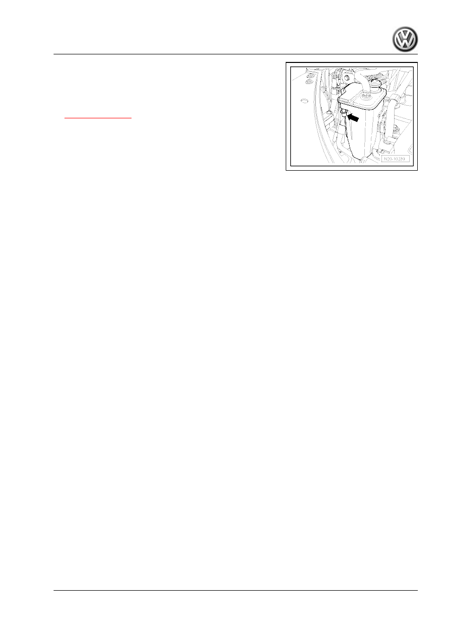
– Seal breather hole -arrow- and operate vacuum pump again

several times. Vacuum must build up.

If vacuum does not build up:
– Also clamp off hose between activated charcoal filter and ac‐

tivated charcoal filter solenoid valve 1 - N80-

⇒ Item 5 (page 407)

 .

– Operate vacuum pump several times.
If vacuum builds up: Renew activated charcoal filter solenoid

valve 1 - N80- .
If vacuum does not build up again, renew activated charcoal filter.

CDAA)    

409

13

Activated charcoal filter system (Golf,

Eos with engine code CBFA, CCTA,

CCTB)

Overview of activated charcoal filter system 

⇒ page 410

Assembly overview - activated charcoal filter system (Golf)

⇒ page 412

 .

Assembly overview - activated charcoal filter system (Eos)

⇒ page 413

 .

Removing and installing activated charcoal filter 

⇒ page 414

Removing and installing fuel system diagnostic pump - V144-

(Golf) 

⇒ page 415

 .

Removing and installing fuel system diagnostic pump - V144-

(Eos) 

⇒ page 416

 .

Checking fuel system for leaks 

⇒ page 416

Note

Hose connections are secured with either spring-type or

clamp-type clips.

Spring-type clip pliers - VAS 6340- or space saving hose clip

pliers - VAS 6362- are recommended for installing and remov‐

ing spring-type clips.

The plug-in connectors for fuel, vacuum and breather lines are

colour coded. There is either a coloured dot on the plug-in con‐

nector or the release button is coloured.

Plug-in connector

Colour code on plug-in connec‐

tor

Fuel supply

black

Fuel return

blue

Breather

white, beige

Vacuum

green

13.1

Overview of activated charcoal filter system

     Rep. gr.20 - Fuel supply system

1 - Separation point

❑ Front right in engine

compartment under

coolant expansion tank

2 - Breather line

❑ white
❑ From activated charcoal

filter to activated char‐

coal filter solenoid valve

1 - N80-

❑ Installation position: On

right under vehicle

❑ Secured to fuel tank.

3 - Breather line

❑ green
❑ From engine to fuel sys‐

tem diagnostic pump -

V144-

❑ Installation position: On

right under vehicle

❑ Secured to fuel tank.

4 - Separation point

❑ Front right on fuel tank in

vicinity of fuel filter

5 - Filler neck
6 - Breather line

❑ From filler neck to acti‐

vated charcoal filter

7 - Air filter

❑ For fuel system diagno‐

sis pump - V144- .

8 - Fuel system diagnostic

pump - V144-

❑ Fitting location: In rear right wheel housing beneath liner
❑ Removing and installing 

⇒ page 415

❑ Checking fuel system for leaks 

⇒ page 416

9 - Connecting cable

❑ From fuel system diagnostic pump - V144- to activated charcoal filter.
❑ Clip onto bracket

10 - Activated charcoal filter

❑ Location: down in spare wheel well
❑ Removing and installing 

⇒ page 414

11 - Separation point

❑ Rear right on fuel tank

12 - Exhaust turbocharger
13 - Brake servo
14 - Vacuum pump
15 - Non-return valve

❑ Location: Arrow points in direction of flow

411

16 - Activated charcoal filter solenoid valve 1 - N80-

❑ Checking ⇒ Vehicle diagnostic tester

17 - Non-return valve

❑ Different versions, allocation ⇒  ETKA (Electronic parts catalogue)

18 - Throttle valve module - J338-

❑ Removing and installing 

⇒ page 488

19 - Intake manifold

13.2

Assembly overview - activated charcoal filter system (Golf)

1 - Fuel
2 - Breather line

❑ Behind wheel housing

liner

3 - Breather line

❑ On underbody.

4 - Breather line

❑ To activated charcoal fil‐

ter solenoid valve 1 -

N80-

❑ Press release button to

pull off

5 - 8 Nm
6 - Activated charcoal filter

❑ Location: down in spare

wheel well

❑ Removing and installing

⇒ page 414

7 - Connecting cable

❑ On underbody.

8 - Connecting cable

❑ Behind wheel housing

liner

9 - 3 Nm
10 - Air filter

❑ For fuel system diagno‐

sis pump - V144- .

11 - Connection hose
12 - Bracket

❑ For fuel system diagno‐

sis pump - V144- .

13 - 2 Nm
14 - 6 Nm
15 - Fuel system diagnostic pump - V144-

❑ Fitting location: In rear right wheel housing beneath liner
❑ Removing and installing 

⇒ page 415

❑ Checking fuel system for leaks 

⇒ page 416

     Rep. gr.20 - Fuel supply system

16 - Connector
17 - Vacuum line

❑ From intake manifold

13.3

Assembly overview - activated charcoal filter system (Eos)

1 - Hose retainer
2 - Breather line

❑ To remove and install,

remove bumper

3 - Air filter

❑ For fuel system diagno‐

sis pump - V144- .

4 - 6 Nm
5 - Bracket

❑ For fuel system diagno‐

sis pump - V144- .

6 - 3 Nm
7 - Retaining plate
8 - Rubber mounting
9 - 8 Nm
10 - Fuel system diagnostic

pump - V144-

❑ Location: Behind rear

right wheel housing

❑ Removing and installing

⇒ page 415

❑ Checking fuel system

for leaks 

⇒ page 416

11 - Hose clamp
12 - Connection hose
13 - Breather line

❑ Behind wheel housing

liner

14 - Fuel
15 - Breather line

❑ To activated charcoal filter solenoid valve 1 - N80-
❑ Press release button to pull off

16 - Breather line

❑ On underbody.

17 - Activated charcoal filter

❑ Location: down in spare wheel well
❑ Removing and installing 

⇒ page 414

18 - Connecting cable

❑ Activated charcoal filter / fuel system diagnostic pump - V144-

19 - Vacuum line

❑ To intake manifold

413

20 - 2 Nm

13.4

Removing and installing activated char‐

coal filter

Special tools and workshop equipment required
♦ Engine and gearbox jack - V.A.G 1383 A-

Removing:
– Remove centre and rear silencers.
– Remove heat shield -arrows-.
– Position engine and gearbox jack - V.A.G 1383 A- below rear

axle to support.

– Loosen securing bolts of rear axle -arrows- and unscrew them

approx. 20mm.

– Lower rear axle slowly using engine and gearbox jack -

V.A.G 1383 A- .

     Rep. gr.20 - Fuel supply system

– Pull off breather lines -A- by pressing release tab.
– Remove bolts -B-.

Note

A reinforcement plate is installed in the Eos. To loosen and tighten

securing bolts -B-, use T-bar and socket 10 mm - 3185- .

– Release retaining tabs -A- using a screwdriver. Turn activated

charcoal filter approx. 90° to right -B- and remove activated

charcoal filter.

Installing:
Installation is carried out in the reverse order. When installing,

note the following:
– Fit breather lines so that they engage audibly.
– Install rear axle ⇒  Running gear; Rep. gr.  42 .
Specified torque

Component

Nm

Activated charcoal filter to body

8

13.5

Removing and installing fuel system di‐

agnostic pump - V144- (Golf)

Removing:
– Remove rear right wheel housing liner ⇒  General body re‐

pairs, exterior; Rep. gr.  66 .

– Pull off breather line -1-.
– Separate electrical connector -2-.
– Pull off breather line -3- by pressing release tab.
– Unscrew nuts -arrows-.
– Detach diagnostic pump with bracket.
Installing:
Installation is carried out in the reverse order. When installing,

note the following:
• The breather line -3- must engage audibly.
– Install rear right wheel housing liner ⇒  General body repairs,

exterior; Rep. gr.  66 .

Specified torques: 

⇒ page 412

415

13.6

Removing and installing fuel system di‐

agnostic pump - V144- (Eos)

Removing:
– Pull off vacuum line -1-, breather line (air outlet) -2- and breath‐

er line (air inlet) -3-.

– Unscrew nuts -arrows-.
– Remove diagnostic pump with bracket and disconnect elec‐

trical connector.

Installing:
Installation is carried out in the reverse order. When installing,

note the following:
♦ Reconnect electrical connector before securing diagnostic

pump with bracket.

♦ The breather line -2- must engage audibly.
Specified torques: 

⇒ page 413

13.7

Checking fuel system for leaks

Special tools and workshop equipment required
♦ Fuel system tester (so-called smoke tester) - KLI 9210-
♦ Adapter hose - KLI 9210/55-1-
♦ Vehicle diagnostic tester
♦ Hose clamps to 25 mm - 3094-

The plug-in connectors for fuel, vacuum and breather lines are

colour coded. There is either a coloured dot on the plug-in con‐

nector or the release button is coloured.

Plug-in connector

Colour code on plug-in connec‐

tor

Fuel supply

black

Fuel return

blue

Breather

white, beige

Vacuum

green

Test specification:
• A leak has been detected by the fuel system diagnostic pump

- V144- .

• Guided fault finding has been performed with the vehicle di‐

agnostic tester .

     Rep. gr.20 - Fuel supply system

Preparation of fuel system tester - KLI 9210- :

Note

The fuel system tester - KLI 9210- may differ in appearance de‐

pending on the version.

– Check on fuel system tester - KLI 9210- if there is enough fluid

in smoke generator.

– Set valve -D- to “Hold”.
– Open nitrogen bottle -H-.
– Connect test hose -G- to self-test connection -B-.
– Set valve -D- to “Test”.
– Regulate pressure to 10 in. H2O (25 mbar) with pressure re‐

ducer -J-.

– Set valve -D- to “Hold”.
– Now pressure must be maintained for at least 2 minutes.

Check tester if pressure is not maintained.

Checking fuel system for leaks:

– Connect adapter hose - KLI 9210/55-1- to breather line -A-.

(colour marking: white)

– Connect measuring hose -G- from fuel system tester - KLI

9210- to adapter hose - KLI 9210/55-1- .

– Set valve -D- to “Hold”.

417

– Connect vehicle diagnostic tester to vehicle.
– Start engine and run at idling speed.
– On vehicle diagnostic tester , select operating mode 

Guided

Functions

.

– Select guided function “Checking tank ventilation system for

leaks”.

– Initiate test.
– Observe pressure gauge - KLI 9210- while test is running.
• Fuel system diagnostic pump - V144- must pump up pressure

in fuel system to at least 7 in. H2O (18 mbar).

The minimum pressure was not reached, but the available pres‐

sure does not drop.
– Switch off ignition and perform a pressure retention test

⇒ page 418

 . If no pressure drop can be detected: Check

vacuum supply of fuel system diagnostic pump - V144-

⇒ page 422

 .

The minimum pressure was not reached and the available pres‐

sure drops immediately:

– Clamp off hose to activated charcoal filter solenoid valve 1 -

N80- using a hose clip -arrow-.

– Repeat check. If the minimum pressure is reached now, renew

activated charcoal filter solenoid valve 1 - N80- .

If the minimum pressure was again not reached and the available

pressure drops immediately:
– Leak in fuel system: Perform “leak detection in fuel system”

⇒ page 420

 .

Switch off ignition if the minimum pressure is reached.
The valve in the fuel system diagnostic pump - V144- closes and

the pressure is retained.
– Observe pressure gauge:
If the pressure does not drop at first, perform a pressure retention

test to localise any potential small leaks 

⇒ page 418

 .

If the pressure drops, clamp off hose to activated charcoal filter

solenoid valve 1 - N80- using a hose clip -arrow-.
– If the pressure does not drop again, renew activated charcoal

filter solenoid valve 1 - N80- .

If the pressure still drops, perform “leak detection in fuel system”

⇒ page 420

 .

Pressure retention test

     Rep. gr.20 - Fuel supply system

– Set valve -D- to “Test”. Set the available pressure to 10 in. H2O

(25 mbar).

– Observe pressure gauge -C- and flow meter -E-. When the

throughput quantity decreases and the pressure increases to

10 in. H2O (25 mbar), the fuel system is filled.

Note

Depending on the filling level of the fuel tank, this process can

take up to 3 minutes.

– Once pressure has stabilised, set valve -D- to “Hold”.
• After 5 minutes the pressure must remain at or above 8 in.

H2O (20 mbar).

If the pressure is not held for at least 5 minutes, localise leak as

follows:

– First check activated charcoal filter solenoid valve 1 - N80- for

leaks. To do this, clamp off hose to activated charcoal filter

solenoid valve 1 - N80- using a hose clip -arrow-.

– Repeat pressure test by setting valve -D- again to “Test”.
– Observe pressure gauge and flow meter. When the through‐

put quantity decreases and the pressure increases to 10 in.

H2O (25 mbar), the fuel system is filled.

– Once pressure has stabilised, set valve -D- to “Hold”.
– If the pressure does not drop again, renew activated charcoal

filter solenoid valve 1 - N80- .

If the pressure still drops, perform “leak detection in fuel system”

⇒ page 420

 .

After completing work, perform guided function “checking fuel

tank ventilation system for leaks” using vehicle diagnostic tester .

419

13.7.1

Leak detection in fuel system

Test specification:
• Procedure for “checking fuel system for leaks” has been com‐

pleted 

⇒ page 416

 .

• Fuel system tester - KLI 9210- is connected to vehicle via

adapter hose - KLI 9210/55-1- .

– Connect fuel system tester - KLI 9210- to vehicle battery.
– Remove rear right wheel housing liner.
– Clamp off hose between fuel system diagnostic pump - V144-

and air filter -arrow-.

Eos

Golf

     Rep. gr.20 - Fuel supply system

– Set valve -D- to “Test”.
– Observe pressure gauge -C- and flow meter -E-. When the

throughput quantity decreases and the pressure increases to

10 in. H2O (25 mbar), the fuel system is filled.

– Once pressure has stabilised, set valve -D- to “Hold”.
• After 5 minutes the pressure must remain at or above 8 in.

H2O (20 mbar).

– If the pressure no longer drops, renew fuel system diagnostic

pump - V144- .

If the pressure is not held for at least 5 minutes or does not build

up, localise leak as follows:
– Fill fuel system with smoke, set valve -D- again to “Test” for

this.

– While fuel system is being filled, press button -I- for smoke

generator for approx. one minute.

The fuel system is now pressurised and filled with smoke.
– Check whether smoke escapes from any fuel system line or

hose. Also check fuel tank cap.

Note

Light up the components and hoses with a strong floodlight. In

the floodlight, smoke is more visible.

For leak detection in accessible areas, an ultrasonic detector

or commercially available leak detecting spray may also be

used.

Depending on how long the fault finding takes, it may be nec‐

essary to press the smoke generator button from time to time.

This ensures that sufficient smoke is present in the fuel sys‐

tem.

To inspect flanges for fuel pump and fuel filter, open assembly

opening in vehicle interior.

– Renew leaking hoses or components.
After completing work, perform guided function “checking fuel

tank ventilation system for leaks” using vehicle diagnostic tester .

13.7.2

Schematic overview of activated charcoal filter system

421

1 - Activated charcoal filter
2 - Location of adapter hose -

KLI 9210/55-1-

❑ For leak detection in fuel

system

3 - Activated charcoal filter sol‐

enoid valve 1 - N80-
4 - Breather line

❑ Throttle valve module -

J338-

5 - Solenoid valve

❑ For fuel system diagno‐

sis pump - V144- .

6 - Vacuum line

❑ To intake manifold

7 - Air filter

❑ For fuel system diagno‐

sis pump - V144- .

8 - Fuel system diagnostic

pump - V144-
9 - Fuel
10 - Cap

13.7.3

Checking vacuum supply of fuel system

diagnostic pump - V144-

Special tools and workshop equipment required
♦ Turbocharger tester - V.A.G 1397A-

♦ T-piece - 251 201 346-
♦ Hose ∅ 6mm

     Rep. gr.20 - Fuel supply system

Note

Fitting location of fuel system diagnostic pump - V144- .

Golf: In rear right wheel housing below wheel housing liner.

Eos: Behind rear right wheel.

Golf:
– Remove rear right wheel and wheel housing liner.
– Pull off vacuum line -1- from fuel system diagnostic pump -

V144- .

– Connect turbocharger tester - V.A.G 1397A- with T-piece and

hose ∅ 6mm, between vacuum line -1- and fuel system diag‐

nostic pump - V144- -2-.

Eos:

– Pull off vacuum line -1- from fuel system diagnostic pump -

V144- .

– Connect turbocharger tester - V.A.G 1397A- with T-piece and

hose ∅ 6mm, between vacuum line -1- and fuel system diag‐

nostic pump - V144- -2-.

All vehicles:
– Switch on measuring range 

I

 (absolute pressure measure‐

ment).

– Connect vehicle diagnostic tester and start engine.
– On vehicle diagnostic tester , select operating mode 

Guided

Functions

.

– Select guided function “Checking tank ventilation system for

leaks”.

– Initiate test.
– Observe display on turbocharger tester - V.A.G 1397A- while

test is running.

• Pressure must pulsate and must remain at or below 0.7 bar

(absolute pressure) during test.

– If pressure exceeds 0.7 bar during test, vacuum supply is too

low. Check vacuum line to intake manifold for possible kinks

or blockages.

423

21 – Turbocharging/supercharging

1

Exhaust turbocharger

Note

Secure all hose connections with hose clips which conform to

production standard.

Hose connections and hoses for charge air system must be

free of oil and grease before assembly. The seal and sealing

surface must be oiled lightly only for plug-in connectors

⇒ page 431

 .

Charge air system must be free of leaks.

Renew self-locking nuts.

Hose clip pliers - VAS 6362- or hose clip pliers - V.A.G 1921-

are recommended for installation of spring-type clips.

Fill turbocharger with engine oil at oil supply line connection.

After installing turbocharger, run engine for about 1 minute at

idling speed and do not rev up immediately. This ensures that

the turbocharger is fully primed with oil.

Observe rules for cleanliness 

⇒ page 280

 .

Assembly overview - turbocharger 

⇒ page 424

 .

Installing hose connections with plug-in connectors

⇒ page 431

 .

Removing and installing turbocharger 

⇒ page 432

 .

Checking turbocharger vacuum unit 

⇒ page 438

 .

Removing and installing vacuum unit for turbocharger

⇒ page 443

 .

Adjusting turbocharger vacuum unit - (engine codes BZB, CGYA,

CDAA) 

⇒ page 439

 .

1.1

Assembly overview - turbocharger

     Rep. gr.21 - Turbocharging/supercharging

Teil I - Engine codes BZB,

CGYA, CDAA, CDAB

⇒ page 426

Teil I - Engine codes CAWB,

CBFA, CCTA, CCTB, CCZA,

CCZB, CCZC, CCZD

⇒ page 427

Teil II - 

⇒ page 428

Teil III - 

⇒ page 429

Teil IV - 

⇒ page 430

425

1.1.1

Part I (engine codes BZB, CGYA, CDAA, CDAB)

1 - Exhaust turbocharger

❑ Can only be renewed to‐

gether with exhaust

manifold and vacuum

unit as one unit

❑ Removing and installing

⇒ page 432

2 - To activated charcoal filter
3 - Vacuum unit for turbocharg‐

er

❑ Checking 

⇒ page 438

❑ Removing and installing

⇒ page 443

❑ Adjusting 

⇒ page 439

4 - Seal

❑ Renew

5 - Banjo union
6 - Banjo bolt

❑ 8 Nm

7 - Hose
8 - Hose
9 - Bolt

❑ 3 Nm

10 - Charge pressure control

solenoid valve - N75-
11 - Hose
12 - Seal
13 - Connection
14 - Retaining clip
15 - Bolt

❑ 9 Nm

16 - Bolt

❑ 7 Nm

17 - Turbocharger air recirculation valve - N249-

❑ Note installation position 

⇒ page 431

18 - Seal

     Rep. gr.21 - Turbocharging/supercharging

1.1.2

Part I (engine codes CAWA, CAWB, CBFA, CCTA, CCTB, CCZA, CCZB,

CCZC, CCZD)

1 - Exhaust turbocharger

❑ Can only be renewed to‐

gether with exhaust

manifold and vacuum

unit as one unit

❑ Removing and installing

⇒ page 432

2 - To activated charcoal filter
3 - Vacuum unit for turbocharg‐

er

❑ Checking 

⇒ page 438

❑ Removing and installing

⇒ page 443

4 - Hose
5 - Hose
6 - Bolt

❑ 3 Nm

7 - Charge pressure control

solenoid valve - N75-
8 - Hose
9 - Connection
10 - Retaining clip
11 - Bolt

❑ 9 Nm

12 - Seal
13 - Turbocharger air recircu‐

lation valve - N249-

❑ Note installation posi‐

tion 

⇒ page 431

14 - Bolt

❑ 7 Nm

15 - Seal

427

Volkswagen Technical Site:   http://vwts.ru   http://vwts.info

1.1.3

Part II

1 - Seal

❑ Renew

2 - Banjo bolt

❑ 33 Nm

3 - Oil supply line
4 - Exhaust turbocharger

❑ Can only be renewed to‐

gether with exhaust

manifold and vacuum

unit as one unit

❑ Removing and installing

⇒ page 432

5 - Bolt

❑ 9 Nm

6 - Bolt

❑ 9 Nm

7 - Seal

❑ Renew

8 - Banjo bolt

❑ 38 Nm

9 - Bolt

❑ 9 Nm

10 - Banjo bolt

❑ 38 Nm
❑ To remove and install,

the turbocharger must

be removed

11 - Seal

❑ Renew

12 - Coolant supply line

❑ To remove and install, the turbocharger must be removed

13 - O-ring

❑ Renew

14 - Bolt

❑ 9 Nm

15 - Seal

❑ Renew

16 - Oil return line
17 - Bolt

❑ 9 Nm

18 - Seal

❑ Renew

     Rep. gr.21 - Turbocharging/supercharging

1.1.4

Part III

1 - Seal

❑ Renew

2 - Nut

❑ Tightening sequence

⇒ page 430

❑ Renew
❑ Coat exhaust manifold

studs with high temper‐

ature paste; high tem‐

perature paste ⇒  ETKA

(Electronic parts cata‐

logue)

3 - Banjo bolt

❑ 38 Nm
❑ To remove and install,

the turbocharger must

be removed

4 - Seal

❑ Renew

5 - Coolant return line

❑ To remove and install,

the turbocharger must

be removed

6 - Bolt

❑ 9 Nm

7 - Exhaust turbocharger

❑ Can only be renewed to‐

gether with exhaust

manifold and vacuum

unit as one unit

❑ Removing and installing

⇒ page 432

8 - Bracket
9 - Bolt

❑ 30 Nm
❑ Coat bolt with high temperature paste; high temperature paste ⇒  ETKA (Electronic parts catalogue)

10 - Bolt

❑ 30 Nm
❑ Coat bolt with high temperature paste; high temperature paste ⇒  ETKA (Electronic parts catalogue)

11 - Nut

❑ Do not loosen to remove turbocharger
❑ Renew
❑ 30 Nm
❑ Coat exhaust manifold studs with high temperature paste; high temperature paste ⇒  ETKA (Electronic

parts catalogue)

12 - Windscreen surround

429

Tightening sequence - turbocharger
– Tighten bolts in sequence -1 to 5- in 4 stages as follows:
– 1. Tighten bolts to 5 Nm.
– 2. Tighten bolts to 12 Nm.
– 3. Tighten bolts to 16 Nm.
– 4. Tighten screws to 25 Nm.

1.1.5

Part IV

Note

Only engine codes BZB, CGYA, CDAA, CDAB have an adjustable

vacuum unit.

1 - Exhaust turbocharger

❑ Can only be renewed to‐

gether with exhaust

manifold and vacuum

unit as one unit

❑ Removing and installing

⇒ page 432

2 - Vacuum unit for turbocharg‐

er

❑ Checking 

⇒ page 438

❑ Removing and installing

⇒ page 443

❑ Adjusting - only engine

codes BZB, CGYA,

CDAA, CDAB

⇒ page 439

 .

3 - Bolt

❑ 10 Nm

4 - Nut

❑ Only engine codes BZB,

CGYA, CDAA, CDAB.

❑ 9 Nm
❑ Secure with sealing

paint

5 - Locking plate

❑ Only engine codes BZB,

CGYA, CDAA, CDAB.

6 - Knurled nut

❑ Only engine codes BZB,

CGYA, CDAA, CDAB.

     Rep. gr.21 - Turbocharging/supercharging

1.1.6

Installation location of turbocharger air

recirculation valve - N249-

– Note installation position -arrows-.

1.2

Fitting hose connections with plug-in

connectors

Caution

The seal for the push-on coupling can be damaged if the re‐

taining  clip  is  in  the  locked  position  during  installation.  This

would result in leaking. Observe installation instructions.

Removing:
– Release plug-in connector by pulling out retaining clip

-arrow-. Separate hose/pipe without tools.

Installing
– If renewed, place seal in groove of charge air hose. Make sure

that the seal is correctly seated in the groove all around the

complete circumference and that it is not twisted.

– Lubricate sealing surface and seal with oil.

– Bring retaining clip to release position -1-.
– Push charge air hose into coupling to stop.
– Bring securing clip to locking position -2- and then push charge

air hose again.

– Check if plug-in connector seats correctly and is properly en‐

gaged by pulling hose.

431

1.3

Removing and installing turbocharger

Special tools and workshop

equipment required

♦ Hose clamp pliers - VAS 6340-
♦ Spring-type clip pliers - VAS 6499-
♦ Bit XZN 10 - T10154-
♦ Bits - T10099-
♦ Engine plug set - VAS 6122-
♦ Torque wrench - V.A.G 1331-
Removing:
– Remove air filter housing 

⇒ page 467

 .

Golf, Eos, Scirocco:
– Remove plenum chamber bulkhead ⇒  General body repairs,

exterior; Rep. gr.  50 ; Plenum chamber bulkhead; Assembly

overview - bulkhead .

All:
– Remove noise insulation ⇒  General body repairs, exterior;

Rep. gr.  50 ; Noise insulation .

     Rep. gr.21 - Turbocharging/supercharging

– Remove front part of right wheel housing liner or front right

wheel housing liner ⇒  General body repairs, exterior; Rep. gr. 

66 ; Wheel housing liner .

– Drain coolant 

⇒ page 241

 .

– Remove engine cover panel.
– Pull connectors from ignition coils and lay wiring harness to

side.

– Disconnect coolant line to coolant expansion tank -arrow-.

– Detach vacuum hose -1- at disconnection point -2-. and lay

line to one side.

– Remove coolant hoses -arrows- from coolant pipe.
– Unbolt earth cable -3- (not engine codes CCZA, CCZB, CCZC,

CCZD) and loosen bolt -4-.

Engine codes BZB, CAWA, CAWB, CGYA, CCZA, CCZB, CCZC,

CCZD, CDAA:
– Press release buttons, pull off air hose -1- and swivel to side.
– Unscrew bolt -arrow- for air pipe.
– Undo hose clip -2- and remove air pipe.

433

Engine codes CBFA, CCTA, CCTB:
– Unscrew bolt -arrow- for air pipe.
– Loosen hose clip -2- and lay air pipe on cylinder head.
All:
– Seal turbocharger openings with engine bung set - VAS

6122- .

– Unscrew bolts -1…3- and remove heat shield together with

coolant pipe.

Note

On 2.0 l engines, unscrew bolt -2- from heat shield using 6 mm

-A- hexagon socket. The hexagon must be at least 5 cm -B- long.

A socket which tapers to 6 mm at the tip is too thick.

– Unscrew oil supply line -4- from turbocharger.

     Rep. gr.21 - Turbocharging/supercharging

– Unscrew bolts -arrows-.
– Remove air pipe (lift clips -items 1 and 2-).

– Remove charge pressure solenoid valve - N75- from turbo‐

charger -arrows-.

– Unscrew bolts -1-, and remove support for turbocharger.

Vehicles with front-wheel drive:
– Remove heat shield for drive shaft on right side -arrows-.
All:
– Remove front exhaust pipe with catalytic converter:

Passat, CC 

⇒ page 526

Golf, Eos, Scirocco 

⇒ page 542

Tiguan 

⇒ page 552

– Separate electrical wiring connections -1 and 2- and place

electrical wiring to one side -arrows-.

435

Vehicles with auxiliary heater:
– Unscrew bolts -1 and 2- and move coolant pipes to the left.
Vehicles with all-wheel drive:
– Raise and tie propshaft to left in tunnel.
– Remove right drive shaft ⇒  Running gear, axles, steering;

Rep. gr.  40 ; Removing and installing drive shafts .

All vehicles:
– Unscrew bolt -1- using bit XZN 10 - T10154- .
– Remove bolt -2-.

– Remove banjo bolt -2- using bits XZN 12 - T10099- and move

coolant pipe to one side.

– Remove bolts -1- on oil return line.
– Remove bolt -3- on oil supply line.

– Disconnect coolant hose -arrow- and move it clear.

     Rep. gr.21 - Turbocharging/supercharging

– Unscrew nuts -arrows-.
– Remove turbocharger and exhaust manifold upwards.
Installing:

Caution

If a mechanical fault is found on the turbocharger, e.g. a de‐

stroyed compressor impeller, just renewing the turbocharger is

not enough. To avoid subsequent damage, the following work

must be carried out:

♦ Check air filter housing, air filter element and intake hoses

for dirt/soiling.

♦ Check the whole charge air path and charge air cooler for

foreign objects. If foreign objects are found in the charge

air system, the charged air routing must be cleaned and

the charge air cooler must be renewed, if necessary.

♦ If bearing damage is evident on the removed turbocharg‐

er, change the engine oil and filter.

Installation is carried out in the reverse order. When installing,

note the following:
♦ Installing hose connections with plug-in connectors

⇒ page 431

 .

♦ Renew seals, gaskets and self-locking nuts.
♦ Fill turbocharger with engine oil at oil supply line connection.
♦ After installing turbocharger, run engine for about 1 minute at

idling speed to ensure that oil is supplied to turbocharger.

♦ The coolant return line 

⇒ Item 5 (page 429)

 must be installed

together with the turbocharger.

♦ Hose connections and hoses for charge air system must be

free of oil and grease before assembly. The seal and sealing

surface must be oiled lightly only for plug-in connectors

⇒ page 431

 .

♦ Secure all hose connections with hose clips which conform to

production standard.

Specified torques 

⇒ page 424

Component


Nm

Exhaust manifold/turbocharger to cylinder

head 

1) 2)

Observe tight‐

ening se‐

quence

⇒ page 430

Oil supply line to turbocharger (M12 banjo bolt)

33

Oil return line to turbocharger

9

Coolant supply line to turbocharger (M14 banjo

bolt, tighten using bits XZN 12 - T10099- )

38

Turbocharger bracket to cylinder block 

2

30

Turbocharger bracket to turbocharger 

2

30

Air intake pipe (right side) to sump

10

Heat shield to cylinder head M8 and M12

20

1)

 Renew nuts.

437

2)

 Use high-temperature paste ⇒  ETKA (Electronic parts cata‐

logue) .

1.4

Checking vacuum unit for turbocharger

Special tools and workshop equipment required
♦ Hand operated vacuum pump - VAS 6213-

Test specification:
♦ Hose from turbocharger via charge pressure control solenoid

valve - N75- to vacuum unit must have through-flow (not

blocked).

♦ Charge pressure control solenoid valve - N75- OK.
Procedure:
– Remove engine cover panel 

⇒ page 141

 .

– Connect hand-operated vacuum pump - VAS 6213- to vacuum

unit -arrow-.

– Move slide ring -1- on hand vacuum pump - VAS 6213- to po‐

sition -B- for “pressure”.

Caution

The pressure must remain at or below 750 mbar! If the pres‐

sure is exceeded, the vacuum unit can be damaged.

– Operate hand vacuum pump - VAS 6213- several times and

observe the linkage.

     Rep. gr.21 - Turbocharging/supercharging

The linkage -A- should start to move at a pressure of approx.

300 mbar and be at its limit stop at a pressure of approx.

700 mbar.
The stroke of the rod is approx. 10 mm.

Note

If no pressure can be built up using hand vacuum pump - VAS

6213- , or if the pressure drops immediately again, check hand

vacuum pump - VAS 6213- and connecting hoses for leaks. If no

fault is found: renew vacuum unit 

⇒ page 443

 .

1.5

Adjusting turbocharger vacuum unit (en‐

gine codes BZB, CGYA, CDAA, CDAB)

Note

This procedure is used only to adjust the vacuum unit. When

checking adjusted vacuum units the values may differ.

Special tools and workshop

equipment required

439

♦ Universal dial gauge holder - VW 387-
♦ Hand operated vacuum pump - VAS 6213-
♦ Pressure regulating valve - VAS 6342-
♦ Turbocharger tester - V.A.G 1397A-
♦ Dial gauge set, 4-part - VAS 6341-
♦ Torque wrench - V.A.G 1783-

♦ Open-end spanner insert AF 10 - V.A.G 1783/1-

Note

Non-adjustable vacuum units are fitted in some vehicles.

The vacuum unit must be adjusted only if the linkage has been

loosened.

Adjustment is carried out when turbocharger is removed.

– Pull hose -arrow- from vacuum unit on turbocharger.
– Detach locking plate above turbocharger linkage.

– Loosen lock nut -2-.

     Rep. gr.21 - Turbocharging/supercharging


Content      ..     12      13      14      15     ..