Volkswagen 4-cyl. injection engine (1.8 and 2.0 l engine, chain drive). Manual (Edition 08.2018) - page 12
 

  Index      Manuals     Volkswagen 4-cyl. injection engine (1.8 and 2.0 l engine, chain drive). Manual (Edition 08.2018). Workshop Manual (Edition 08.2018)


Search            copyright infringement  


Content      ..     10      11      12      13     ..


Volkswagen 4-cyl. injection engine (1.8 and 2.0 l engine, chain drive). Manual (Edition 08.2018) - page 12


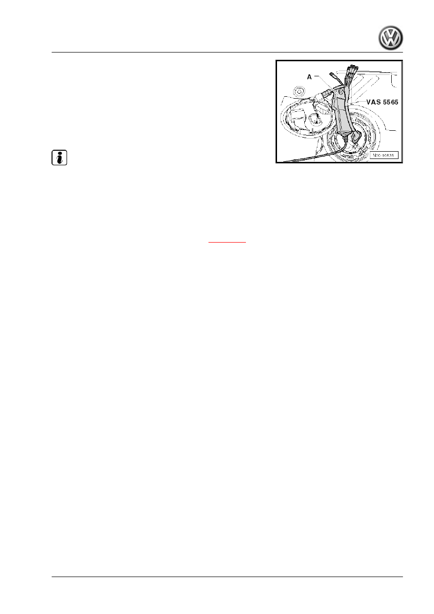
– Connect test instrument adapter/DSO (5-pin) - VAS 5565- to

connector and fuel delivery unit.

– Connect pick-up clamp -A- to red terminal with lettering “pick-

up clamp” for test instrument adapter/DSO (5-pin) - VAS

5565- .

– Start engine and run at idling speed.
– Measure current draw of fuel pump.
• Specification: max. 10 amps

Note

The starting current for the fuel pump can be briefly above

specifications when starting the engine.

If the fault in the fuel system is not always evident, the check

can also be carried out during a road test. A 2nd person is

required to do this, however.

If the current draw is exceeded:
– Fuel pump defective, renew fuel delivery unit 

⇒ page 326

 .

345

8

Repairing fuel supply system (Golf,

Eos, Scirocco)

Note

Fuel hoses on the engine must only be secured with spring-

type clips which conform to the production standard.

Spring-type clip pliers - VAS 6340- or space saving hose clip

pliers - VAS 6362- are recommended for installing and remov‐

ing spring-type clips.

Safety precautions when working on fuel supply system

⇒ page 278

 .

Comply with rules for cleanliness 

⇒ page 280

 .

Removing and installing fuel delivery unit 

⇒ page 346

 .

Removing and installing fuel gauge sender - G- 

⇒ page 349

 .

Checking fuel pump - G6- 

⇒ page 350

 .

8.1

Removing and installing fuel delivery

unit

Special tools and workshop equipment required
♦ Special wrench - T10202-

♦ Torque wrench (40 to 200 Nm) - V.A.G 1332-

     Rep. gr.20 - Fuel supply system

Removing:

Caution

Condition:

• The fuel tank must not be more than 

3

/4 full. This ensures

that the fill level is below the flange of the fuel delivery unit.

Note

When replacing fuel delivery unit, check fuel tank for heavy

soiling and clean if necessary.

If necessary, drain fuel tank using fuel extractor - VAS 5190- .

Note safety precautions before beginning work 

⇒ page 278

 .

Observe rules for cleanliness 

⇒ page 280

 .

Assembly overview - fuel tank 

⇒ page 291

 .

– Remove bench seat ⇒  General body repairs, interior; Rep. gr. 

72 ; Removing and installing bench seat .

– Remove cover -1- with fuel pump control unit - J538- -2- from

fuel delivery unit.

– First check that the connector -arrow- is fitted securely by pull‐

ing the connector without pressing the catch. The connector

can cause a fault if it has not been fitted correctly.

– Now pull off connector.
– Check the contacts on the connector and on the fuel delivery

unit for damage.

WARNING

Fuel supply line is pressurised. Wear protective goggles and

protective clothing to avoid injury and contact with the skin.

Wrap  a  cloth  around  the  connection  before  loosening  hose

connections. Then release pressure by carefully pulling hose

off connection.

347

– Pull fuel lines -1- and -2- off the flange.

Note

Press in securing ring to release the fuel lines.

On vehicles with auxiliary heater, the connector and the fuel

line of the metering pump - V54- must also be disconnected.

– Open locking ring using key - T10202- and raise flange slightly.

Caution

Do not cant key - T10202- and press against locking ring firmly.

If the key slips off, the fuel delivery unit can be damaged.

– Pull fuel delivery unit and seal out of the opening in fuel tank.

Note

If delivery unit is to be renewed, drain old delivery unit before

disposal.

Observe disposal regulations!

Installing:
– Renew seal.
– Insert seal for fuel delivery unit dry into opening of fuel tank.
– Coat inner side of seal with fuel.
– When inserting fuel delivery unit, ensure that fuel gauge send‐

er is not bent.

– Press sealing flange down against spring pressure, and move

sealing flange to installation position.

• Tab -2- on flange must be between lugs -1- and -3- on fuel

tank.

• -Arrow- points in direction of travel.
– Tighten sealing flange.
• Specified torque: 110 Nm

     Rep. gr.20 - Fuel supply system

– Reconnect supply line-1- (black).
– Reconnect fuel return line -2- (blue or blue marking).

– Reconnect connector -arrow-.
– Ensure push-fit couplings and electrical connectors are se‐

cured properly by pulling.

Further assembly is performed in the reverse order of removal.

During this procedure, observe the following:

♦ Observe installation position of fuel feed line to auxiliary heater

⇒  Auxiliary heater; Rep. gr.  82 ; Fuel feed Thermo Top V .

♦ The -arrow- on the cover points forwards.

8.2

Removing and installing fuel gauge

sender - G-

Removing:
– Remove fuel delivery unit 

⇒ page 346

 .

– Pull fuel gauge sender - G- slightly to side and upwards at the

same time.

349

– If the sender cannot be released in this way, the retaining tabs

-arrows- must also be pushed to the side slightly.

– Note colour co-ordination of cables for reinstallation.

– Release electrical connectors -1 to 3- and pull them off. Then

bend back locking lugs of connectors.

Installing:

– Connect connectors -1…3-. Observe colour co-ordination.
– Check connectors are secured properly by pulling.
– Insert fuel gauge sender - G- into guide on fuel delivery unit

and press down until it engages.

– Install fuel delivery unit 

⇒ page 346

 .

8.3

Checking fuel pump - G6-

     Rep. gr.20 - Fuel supply system

Special tools and workshop

equipment required

♦ Pressure gauge - VAS 6550-
♦ Remote control - V.A.G 1348/3A-
♦ Test instrument adapter/DSO (5-pin) - VAS 5565-
♦ Multimeter - V.A.G 1715-
♦ Special wrench - T10202-
♦ Torque wrench - V.A.G 1332-
♦ Measuring container, capacity: 3 litres

8.3.1

Checking function and voltage supply

Test conditions:
• Battery voltage at least 11.5 V.
• Fuse for Fuel pump control unit - J538- OK.
• Fuel pump control unit - J538- OK.

351

Test sequence

Note

Function of fuel pump is checked using final control diagnosis.

If the final control diagnosis is to be carried out several times

in succession, it may be necessary to start the engine briefly

before repeating the final control diagnosis.

– Connect vehicle diagnostic tester as follows:
– Push diagnosis cable connector onto diagnosis connection in

driver footwell.

– Switch ignition on.
– Press buttons on display one after the other for 

Vehicle

self-diagnosis

Engine electronics

 and 

Final con-

trol diagnosis

.

– Press right arrow button 

 on display up to final control diag‐

nosis for fuel pump electronics.

The fuel pump must now run slowly up to maximum speed.

Note

The fuel pump runs very quietly.

– Switch off ignition.
If fuel pump does not run:
– Remove bench seat ⇒  General body repairs, interior; Rep. gr. 

72 ; Removing and installing bench seat .

– Pull connector off fuel pump control unit - J538- .

– Check voltage supply between contacts -1- and -6- using mul‐

timeter - V.A.G 1715- .

• Specification: approx. battery voltage
Voltage supply not OK:
– Locate and eliminate open circuit referring to current flow di‐

agram ⇒ Current flow diagrams, Electrical fault finding and

Fitting locations.

Voltage supply OK:

     Rep. gr.20 - Fuel supply system

– Remove cover -1- with fuel pump control unit - J538- -2- from

fuel delivery unit.

– First check that the connector -arrow- is fitted securely by pull‐

ing the connector without pressing the catch. If connector was

not inserted correctly, repeat functional check of fuel pump.

– Now pull off connector.
– Check the contacts on the connector and on the fuel delivery

unit for damage.

WARNING

Fuel supply line is pressurised. Wear protective goggles and

protective clothing to avoid injury and contact with the skin.

Wrap  a  cloth  around  the  connection  before  loosening  hose

connections. Then release pressure by carefully pulling hose

off connection.

– Pull fuel lines -1- and -2- off the flange.

Note

Press in securing ring to release the fuel lines.

On vehicles with auxiliary heater, the connector and the fuel

line of the metering pump - V54- must also be disconnected.

– Open locking ring using key - T10202- .

Caution

Do not cant key - T10202- and press against locking ring firmly.

If the key slips off, the fuel delivery unit can be damaged.

– Check that electrical wires between flange and fuel pump are

connected.

If no open circuit can be found:
– Fuel pump defective, renew fuel delivery unit 

⇒ page 346

 .

353

8.3.2

Checking fuel pressure

Note

The fuel pressure must be checked by means of the final con‐

trol diagnosis. If the fuel pressure is measured at idling speed,

it may deviate from the specification.

If the final control diagnosis is to be carried out several times

in succession, it may be necessary to start the engine briefly

before repeating the final control diagnosis.

WARNING

Fuel supply line is pressurised. Wear protective goggles and

protective clothing to avoid injury and contact with the skin.

Wrap  a  cloth  around  the  connection  before  loosening  hose

connections. Then release pressure by carefully pulling hose

off connection.

– Pull off supply line (metal coupling) -arrow- and catch escaping

fuel with a cloth.

Note

Press in securing ring to release fuel line.

– Connect pressure tester - VAS 6550- to fuel supply line with

adapter - VAS 6550/1- and -VAS 6550/2- .

– Make sure that drain tap is closed and cut-off taps are open.
– Actuate fuel pump with final control diagnosis to build up fuel

pressure.

– Read fuel pressure on pressure gauge.
• Specification: 4.0 to 7.0 bar
If fuel pressure is OK, check holding pressure 

⇒ page 358

 .

If the specification is exceeded:
– Check return line between fuel filter and fuel pump for kinks

and blockages.

If no fault is found:
– Pressure limit valve in fuel filter is defective. Renew fuel filter.
If specification is not obtained
– Check fuel pressure upstream of fuel filter; proceed as follows:

     Rep. gr.20 - Fuel supply system

– Pull fuel supply line -arrow- off fuel filter.

– Connect pressure tester - VAS 6550- between fuel filter and

fuel supply line with adapter - VAS 6550/1- and -VAS 6550/2- .

– Make sure that drain tap is closed and cut-off taps are open.
– Switch ignition on and activate the fuel pump with the final

control diagnosis function.

– While the fuel pump is operating, close the shut-off tap -A-.

Pressure must rise to at least 7.0 bar. When 7.0 bar is reached,

open shut-off tap again immediately.

If pressure has risen:
– Fuel pump is OK. Pressure limiting valve in fuel filter is defec‐

tive. Renew fuel filter.

If pressure does not rise:
– Fuel pump defective, renew fuel delivery unit 

⇒ page 346

 .

355

8.3.3

Checking fuel pressure when the engine

is running (engine codes CCZA, CCZB,

CDAA, CDAB)

Note

If a complaint is made about the vehicle's performance, the

reason may be that the fuel pressure is too low. Faults in the

high-pressure section may also be caused by inadequate fuel

pressure in the low-pressure section. This check determines

the fuel pressure in the high-pressure and low-pressure sec‐

tions during a road test. Fuel pressure in the high-pressure

section is read from the engine control unit. The lowest fuel

pressure is measured by the pressure tester - VAS 6550- and

reported to the vehicle diagnosis and service information sys‐

tem - VAS 5052 B- .

This test can be part of “Guided Fault Finding” if an entry has

been made in the event memory. However, it can also be star‐

ted in the vehicle diagnosis and service information system -

VAS 5052 B- by means of “Functions and component

selection”.

Special tools and workshop equipment required
♦ Pressure gauge - VAS 6550-
♦ Hose adapters - VAS 6550/1- and -VAS 6550/2-
♦ Vehicle diagnosis and service information system - VAS 5052

B-

♦ Connector cable - VAS 5051/66-
– Remove bench seat ⇒  General body repairs, interior; Rep. gr. 

72 ; Removing and installing bench seat .

– Remove cover -1- with fuel pump control unit - J538- -2- from

fuel delivery unit.

– First check that the connector -arrow- is fitted securely by pull‐

ing the connector without pressing the catch. The connector

can cause a fault if it has not been fitted correctly.

WARNING

The fuel line is under pressure.
Fuel poses danger of injury to eyes and skin.
Wear protective goggles and protective clothing to avoid injury

and contact with the skin. Wrap a cloth around the connection

before loosening hose connections. Then reduce pressure by

carefully opening the connection.

     Rep. gr.20 - Fuel supply system

– Pull off supply line -arrow- and catch escaping fuel with a cloth.

Note

Press in securing ring to release fuel line.

– Connect pressure tester - VAS 6550- to fuel supply line with

adapter - VAS 6550/2- and -VAS 6550/1- .

– Fit connector cable - VAS 5051/66- to pressure tester - VAS

6550- and to vehicle diagnosis and service information system

- VAS 5052 B- .

– Make sure that drain tap is closed and cut-off taps are open.
– Switch on pressure tester - VAS 6550- .
If the fuel pressure test is carried out within “Guided Fault Find‐

ing”, follow the instructions of the diagnostic tester.
If the fuel pressure test is carried out without “Guided Fault Find‐

ing”, proceed as follows:
– Connect vehicle diagnosis and service information system -

VAS 5052 B- to vehicle.

– Select 

Guided Fault Finding

 in -VAS 5052 B- .

– Carry out identification of vehicle.
– Using the 

GoTo

 button, select the following menu options one

after the other:

Function/component selection

Drive

Engine

24 Mixture preparation/injection

Mechanical components

High-pressure pump

– Follow instructions on vehicle diagnosis and service informa‐

tion system - VAS 5052 B- .

WARNING

Test instruments and measuring equipment must always be

secured to the rear seat and operated by a second person from

this location.

357

8.3.4

Checking holding pressure

• Fuel pressure OK and pressure tester - VAS 6550- connected.

Check fuel pressure 

⇒ page 354

 .

Test sequence
– Actuate fuel pump with final control diagnosis to build up fuel

pressure.

– Read fuel pressure on pressure gauge.
• Specification: 4.0 to 7.0 bar
– End self-diagnosis, and switch off ignition.
– Watch pressure drop on pressure gauge. Pressure must re‐

main above 3.0 bar for 10 minutes.

If the pressure drops further:
– Actuate fuel pump with final control diagnosis to build up fuel

pressure.

– After pressure has built up, close cut-off tap -B- of pressure

tester immediately. Lever is then at right angle to direction of

flow.

If the pressure does not drop now (leak on engine side)

⇒ page 359

 .

If the pressure drops again (leak on fuel tank side):
Leak must be sought on fuel tank side; proceed as follows:
– Check fuel supply line to fuel filter for leaks.
If no fault is found on the fuel line:
– Check pressure retention valve in fuel delivery unit. Proceed

as follows:

– Pull fuel supply line -arrow- off fuel filter.

     Rep. gr.20 - Fuel supply system

– Connect pressure tester - VAS 6550- between fuel filter and

fuel supply line with adapter - VAS 6550/1- and -VAS 6550/2- .

– Make sure that drain tap is closed and cut-off taps are open.
– Actuate fuel pump with final control diagnosis to build up fuel

pressure.

– Read fuel pressure on pressure gauge.
• Specification: 4.0 to 7.0 bar

– After pressure has built up, close cut-off tap -A-.
– Watch pressure drop on pressure gauge. Pressure must re‐

main above 3.0 bar for 10 minutes.

If the pressure drops:
– Pressure retention valve in fuel pump defective; renew fuel

delivery unit 

⇒ page 346

 .

If the pressure does not drop:
– Pressure retention valve in fuel filter is OK, pressure limiting

valve in fuel filter is defective. Renew fuel filter.

If the pressure does not drop now (leak on engine side):

Note

Search for leak on engine side. Repeat holding pressure test. This

time, close shut-off tap -A- to check whether leak actually is on

engine side.

– If there is a leak on the engine side, carry out external check

of the fuel pipes and high-pressure pump for leaks.

If no fault can be determined, check the injectors for leaks:
– Remove spark plugs. Open shut-off valves -A- and -B-. Ac‐

tuate fuel pump with final control diagnosis.

– Check through spark plug holes whether fuel has collected on

the piston crown due to a leaking injector.

8.3.5

Checking fuel delivery rate (engine co‐

des CAWA, CAWB, CBFA, CCTA,

CCTB, BZB, CGYA)

– Remove bench seat ⇒  General body repairs, interior; Rep. gr. 

72 ; Removing and installing bench seat .

359

– Remove cover -1- with fuel pump control unit - J538- -2- from

fuel delivery unit.

– First check that the connector -arrow- is fitted securely by pull‐

ing the connector without pressing the catch. The connector

can cause a fault if it has not been fitted correctly.

– Now pull off connector.
– Check the contacts on the connector and on the fuel delivery

unit for damage.

– Connect test instrument adapter/DSO (5-pin) - VAS 5565- to

connector and fuel delivery unit.

– Connect remote control - V.A.G 1348/3A- to adapter - VAS

5565- and to battery positive terminal clamp in the engine

compartment.

Note

This step serves only to have the fuel pump running when the

engine is stopped.

WARNING

Fuel supply line is pressurised. Wear protective goggles and

protective clothing to avoid injury and contact with the skin.

Wrap  a  cloth  around  the  connection  before  loosening  hose

connections. Then release pressure by carefully pulling hose

off connection.

– Pull off supply line (metal coupling) -arrow- and catch escaping

fuel with a cloth.

Note

Press in securing ring to release the fuel lines.

     Rep. gr.20 - Fuel supply system

– Connect pressure tester - VAS 6550- to fuel supply line with

adapter - VAS 6550/2- . Hold adapter - VAS 6550/1- in a

measuring container.

– Make sure that drain tap is closed and cut-off taps are open.

WARNING

Danger of spraying! Wear protective goggles and protective

clothing to avoid injury and contact with the skin. Hold container

in front of open connection of pressure tester.

– Operate remote control - V.A.G 1348/3A- . Then slowly close

shut-off tap -arrow- until a pressure of 4 bar is displayed on

pressure gauge. From this point on do not move position of

shut-off tap.

– Drain measuring container.

– The quantity delivered by the fuel pump depends on the bat‐

tery voltage. Therefore, also connect multimeter - V.A.G 1715-

to outputs -1 and 5- of test instrument/DSO adapter 5-pin -

VAS 5565- .

– Operate remote control for 60 seconds while measuring volt‐

age at fuel pump.

– Compare quantity of fuel delivered with specification.
*) Minimum delivery rate cm³/60 s
**) Voltage at fuel pump with engine not running and pump run‐

ning.
Reading example:
During the test a voltage of 10.5 volts is measured. This equates

to a minimum delivery rate of approx. 1200 cm³/60 s
If specification is not obtained
– Check fuel lines for possible restrictions (kinks) or blockages.
If no fault is found:
– Remove cap from fuel filler neck and repeat check. If fuel de‐

livery rate is now reached, check fuel tank breather.

If reading again does not match specification:
– Check fuel filter (proceed as follows):

WARNING

Fuel supply line is pressurised. Wear protective goggles and

protective clothing to avoid injury and contact with the skin.

Wrap  a  cloth  around  the  connection  before  loosening  hose

connections. Then release pressure by carefully pulling hose

off connection.

361

– Pull fuel supply line -arrow- off fuel filter.

– Connect pressure tester - VAS 6550- to fuel supply line with

adapter - VAS 6550/1- . Hold adapter - VAS 6550/2- in a

measuring container.

– Make sure that drain tap is closed and cut-off taps are open.
– Operate remote control - V.A.G 1348/3A- . Then slowly close

shut-off tap -arrow- until a pressure of 4 bar is displayed on

pressure gauge. From this point on do not move position of

shut-off tap.

– Drain measuring container.
– Repeat delivery rate check.
If the minimum delivery rate is now attained:
– Renew fuel filter.
If the minimum delivery rate is again not attained
– Remove fuel delivery unit and check filter strainer for soiling.
Only if still no fault has been detected:
– Renew fuel delivery unit.
If the fuel delivery rate has been attained but a fault is still sus‐

pected in the fuel supply system (e.g. intermittent failure of fuel

supply system):
– Measure current draw of fuel pump 

⇒ page 364

 .

8.3.6

Checking fuel delivery rate (engine co‐

des CCZA, CCZB, CDAA, CDAB)

Note

The fuel delivery rate must first be checked in the engine com‐

partment with the help of the function “Checking fuel delivery rate,

quick test”. If the minimum delivery rate is not achieved, a 2nd

measurement must be carried out at the flange of the fuel delivery

unit.

Checking fuel delivery rate in engine compartment:
– Connect vehicle diagnosis and service information system -

VAS 5052 B- to vehicle.

– Select 

Guided Functions

 in -VAS 5052 B- .

– Carry out identification of vehicle.
– Select 

Engine

.

– Select 

Checking fuel delivery rate, quick test

.

     Rep. gr.20 - Fuel supply system

– Follow instructions on vehicle diagnosis and service informa‐

tion system - VAS 5052 B- .

Checking fuel delivery rate at flange:
• The guided function “Checking fuel delivery rate, quick test”

has been carried out ⇒ Vehicle diagnostic tester

• The remote control - V.A.G 1348/3A- and test instrument

adapter/DSO (5-pin) - VAS 5565- have been connected to the

fuel delivery unit.

• Battery charger connected
• Filling level in fuel tank above reserve
Test sequence

WARNING

The fuel line is under pressure.
Fuel poses danger of injury to eyes and skin.
Wear protective goggles and protective clothing to avoid injury

and contact with the skin. Wrap a cloth around the connection

before loosening hose connections. Then reduce pressure by

carefully opening the connection.

– Pull fuel supply line -arrow- off fuel filter.

– Connect pressure tester - VAS 6550- to fuel supply line with

adapter - VAS 6550/1- . Hold adapter - VAS 6550/2- in a

measuring container.

– Make sure that drain tap is closed and cut-off taps are open.
– Operate remote control - V.A.G 1348/3A- . Then slowly close

shut-off tap -arrow- until a pressure of 4 bar is displayed on

pressure gauge. From this point on do not move position of

shut-off tap.

– Drain measuring container.

363

– The quantity delivered by the fuel pump depends on the bat‐

tery voltage. Therefore, connect multimeter - V.A.G 1715- to

wires -1- and -5- of adapter - VAS 5565- in addition.

– Operate remote control for 60 seconds while measuring volt‐

age at fuel pump.

– Compare quantity of fuel delivered with specification.
*) Minimum delivery rate cm³/60 s
**) Voltage at fuel pump with engine not running and pump run‐

ning.
Reading example:
During the test a voltage of 10.5 volts is measured. This equates

to a minimum delivery rate of approx. 1200 cm³/60 s
If specification is not obtained
– Remove cap from fuel filler neck and repeat check. If fuel de‐

livery rate is now reached, check fuel tank breather.

If reading again does not match specification:
– Remove fuel delivery unit and check filter strainer for soiling.
– If no fault is found here either, renew flange with fuel filter.
– Repeat check.
If reading again does not match specification:
– Fuel pump defective, renew fuel delivery unit 

⇒ page 326

 .

If fuel delivery rate has been attained, but nevertheless you sus‐

pect a fuel supply system fault (e.g. intermittent failure of fuel

supply system): Check fuel pressure with the engine running

⇒ page 336

 .

8.3.7

Checking current consumption

– Remove bench seat ⇒  General body repairs, interior; Rep. gr. 

72 ; Removing and installing bench seat .

– Remove cover -1- with fuel pump control unit - J538- -2- from

fuel delivery unit.

     Rep. gr.20 - Fuel supply system

– First check that the connector -arrow- is fitted securely by pull‐

ing the connector without pressing the catch. The connector

can cause a fault if it has not been fitted correctly.

– Now pull off connector.
– Check the contacts on the connector and on the fuel delivery

unit for damage.

– Connect test instrument adapter/DSO (5-pin) - VAS 5565- to

connector and fuel delivery unit.

– Connect pick-up clamp -A- to red terminal with lettering “pick-

up clamp” for test instrument adapter/DSO (5-pin) - VAS

5565- .

– Start engine and run at idling speed.
– Measure current draw of fuel pump.
• Specification: max. 9 amps

Note

The starting current for the fuel pump can be briefly above

specifications when starting the engine.

If the fault in the fuel system is not always evident, the check

can also be carried out during a road test. A 2nd person is

required to do this, however.

If the current draw is exceeded:
– Fuel pump defective, renew fuel delivery unit 

⇒ page 346

 .

365

9

Repairing fuel supply (Tiguan)

Note

Fuel hoses on the engine must only be secured with spring-

type clips which conform to the production standard.

Hose clip pliers - VAS 6362- or hose clip pliers - V.A.G 1921-

are recommended for installation of spring-type clips.

Safety precautions when working on fuel supply system

⇒ page 278

 .

Comply with rules for cleanliness 

⇒ page 280

 .

Removing and installing fuel delivery unit 

⇒ page 366

 .

Removing and installing fuel gauge sender - G- 

⇒ page 370

 .

Removing and installing suction jet pump 

⇒ page 371

 .

Removing and installing fuel gauge sender 2 - G169-

⇒ page 373

 .

Removing and installing fuel pump control unit - J538-

⇒ page 374

 .

Check fuel pump 

⇒ page 375

 .

9.1

Removing and installing fuel delivery unit

     Rep. gr.20 - Fuel supply system

Special tools and workshop

equipment required

♦ Assembly tool - T10118-
♦ Special wrench - T10202-
♦ Torque wrench - V.A.G 1332-
♦ Fuel extractor - VAS 5190-
Removing:

Caution

Condition:

• The fuel tank must not be more than 

1

/2 full. This ensures

that the fill level is below the flange of the fuel delivery unit.

367

Note

When replacing fuel delivery unit, check fuel tank for heavy

soiling and clean if necessary.

If necessary, drain fuel tank using fuel extractor - VAS 5190- .

Note safety precautions before beginning work 

⇒ page 278

 .

Observe rules for cleanliness 

⇒ page 280

 .

– Remove bench seat ⇒  General body repairs, interior; Rep. gr. 

72 ; Rear seats; Removing and installing bench seat / individ‐

ual seats .

– Unclip cover -1- (which is on right side as seen in direction of

travel) at retaining tabs -arrows- using removal wedge - 3409- .

– First ensure that 5-pin wiring connection -1- is secure by pull‐

ing the connector without pressing the catch. The connector

can cause a fault if it has not been fitted correctly.

– Now pull off connectors -1-.
– Check the contacts on the connector and on the fuel delivery

unit for damage.

– Release connector -arrow- on fuel pump control unit - J538-

using assembly tool - T10118- and pull it off.

WARNING

The fuel line is under pressure.
Fuel poses danger of injury to eyes and skin.
Wear protective goggles and protective clothing to avoid injury

and contact with the skin. Wrap a cloth around the connection

before loosening hose connections. Then reduce pressure by

carefully opening the connection.

     Rep. gr.20 - Fuel supply system

– Pull off supply line -2- and catch escaping fuel with a cloth.

– Open locking ring using key - T10202- .

Caution

Do not cant key - T10202- and press against locking ring firmly.

If the key slips off, the fuel delivery unit can be damaged.

– Slightly raise fuel delivery unit and remove seal out from aper‐

ture in fuel tank.

– Release fuel hoses on delivery unit -arrows- and pull delivery

unit out of fuel tank.

Note

If delivery unit is to be renewed, drain old delivery unit before dis‐

posal.

Installing

– Reconnect fuel hoses -arrows-. Ensure that fuel hoses engage

audibly and check to ensure firm seating by pulling!

– Further installation of the fuel delivery unit is carried out in re‐

verse order of removal.

369

Note

Fuel hoses are allocated to respective unions.

Ensure plug-in connectors are secured properly by pulling.

When inserting the fuel delivery unit, ensure that the fuel

gauge sender - G- is not bent.

Insert seal for fuel delivery unit dry into opening of fuel tank.

Moisten seal with fuel only when installing fuel delivery unit.

Note installation position of flange for fuel delivery unit: tab

-1- must point in direction of travel. The fuel delivery unit flange

can only be installed in this position.

9.2

Removing and installing fuel gauge

sender G

– Remove fuel delivery unit 

⇒ page 366

 .

Special tools and workshop equipment required
♦ Welding wire (2 mm thick)
– Bend an 80 mm long welding wire as shown.
Dimension -a- = 10 mm
Dimension -b-: 70 mm
Removing
– Release connector of wiring for fuel gauge sender and dis‐

connect it.

– Press welding wire -1- in direction of -arrow- into recess be‐

neath sender.

– At the same time, push fuel gauge sender -2- from guides in

direction of -arrow-.

Installing
– Insert fuel sender into guides on fuel delivery unit and press

downwards until it engages.

– Reconnect connector and check that it has engaged correctly.
– Install fuel delivery unit 

⇒ page 366

 .

     Rep. gr.20 - Fuel supply system

9.3

Removing and installing suction-jet

pump, fuel filter and pressure limitation

valve

Special tools and workshop equipment required
♦ Special wrench - T10202-

♦ Torque wrench (40 to 200 Nm) - V.A.G 1332-

Note

On vehicles with four-wheel drive, fuel must be pumped from

the area of fuel gauge sender 2 - G169- to the fuel pump unit

due to the shape of the fuel tank. To do so, a suction-jet pump

pumps fuel from left chamber to right chamber of fuel tank.

The fuel delivery unit must first be removed to remove the

suction-jet pump.

The left flange consists of suction-jet pump, fuel filter, pressure

limitation valve and fuel gauge sender 2 - G169- Only fuel

gauge sender 2 - G169- can be renewed separately.

Checking fuel gauge sender 2 - G169- is only necessary when

the engine stops due to lack of fuel, even though the fuel

gauge shows that the tank is still 1/4 full.

Removing:
– Remove bench seat ⇒  General body repairs, interior; Rep. gr. 

72 ; Removing and installing bench seat .

– Remove fuel delivery unit 

⇒ page 366

 .

– Remove left cover (as seen facing direction of normal travel)

from fuel gauge sender 2 - G169- .

– First check that the connector is fitted securely by pulling the

connector without pressing the catch. The connector can

cause a fault if it has not been fitted correctly.

371

– Pull connector -1- off left flange.

– Open locking ring using key - T10202- .
– Slightly raise flange and remove seal out from opening in fuel

tank.

– Pull flange together with fuel gauge sender 2 - G169- out of

fuel tank.

– Check fuel lines for kinks and damage.
– Additionally check suction-jet pump and fuel tank for possible

soiling.

Installing

Caution

When installing do not bend fuel gauge sender 2 - G169- float

arm.

– Install flange together with fuel gauge sender 2 - G169- in fuel

tank. The lug on the flange points in direction of travel.

– Place fuel lines in right chamber of fuel tank ensuring they are

not kinked.

– Fit new seal for flange in fuel tank opening (seal should be

dry). Only moisten the inside (contact with flange) with fuel.

– Note installation position of fuel gauge sender 2 - G169-

⇒ page 306

– Check correct position of seal.

– Tighten locking ring using wrench - T10202- . Specified torque:

110 Nm.

     Rep. gr.20 - Fuel supply system

– Reconnect connector -1- and check it is secured properly by

pulling.

– Install fuel delivery unit 

⇒ page 366

 .

Further assembly is performed in the reverse order of removal.

9.4

Removing and installing fuel gauge

sender 2 - G169-

– Removing and installing suction-jet pump (Tiguan)

⇒ page 371

 .

Special tools and workshop equipment required
♦ Welding wire (2 mm thick)
– Bend an 80 mm long welding wire as shown.
Dimension -a- = 10 mm
Dimension -b-: 70 mm
Removing
– Release connectors for lines for fuel gauge sender 2 - G169-

-2- and pull off.

– Press welding wire -1- in direction of -arrow- into recess be‐

neath sender.

– At the same time, push fuel gauge sender 2 - G169- -2- from

guides in direction of -arrow-.

Installing
– Insert fuel gauge sender 2 - G169- into guides and press down

until it engages.

– Reconnect connector and check that it has engaged correctly.
– Install suction-jet pump 

⇒ page 371

 .

373

9.5

Removing and installing fuel pump con‐

trol unit - J538-

Note

The fuel pump control unit - J538- is installed on the fuel tank.

Special tools and workshop equipment required
♦ Commercially available flat-bladed screwdriver (blade width

120 mm)

♦ Removal wedge - 3409-

Fuel pump control unit - J538- fitting location
1 - Bracket for fuel pump control unit - J538-
2 - Fuel pump control unit - J538-
3 - Connector
Removing
– Remove bench seat ⇒  General body repairs, interior; Rep. gr. 

72 ; Rear seats; Removing and installing bench seat / individ‐

ual seats .

– Unclip cover -1- (which is on right side as seen in direction of

travel) at retaining tabs -arrows- using removal wedge - 3409- .

     Rep. gr.20 - Fuel supply system

– Pull off connector -3- for fuel pump control unit - J538- .
– Check contacts on plug and on fuel delivery unit for damage.

– Slide screwdriver -2- into bracket recess -1- directly above

plug.

– Swivel screwdriver in direction of -arrow-.

– Press screwdriver down in direction of -arrow- and pull control

unit out of bracket at plug at same time.

– First check that the connector is fitted securely by pulling the

connector without pressing the catch. The connector can

cause a fault if it has not been fitted correctly.

– Pull connector off control unit.
Installing

– Reconnect connector -3- to control unit -2- and check engage‐

ment (pull back).

– Slide control unit -2- into bracket -1- until it engages.
Further installation is carried out in reverse order of removal.

9.6

Checking fuel pump

Note

When replacing fuel delivery unit, check fuel tank for heavy soiling

and clean if necessary.

375


Content      ..     10      11      12      13     ..