Volkswagen 4-cyl. injection engine (1.8 and 2.0 l engine, chain drive). Manual (Edition 08.2018) - page 10
 

  Index      Manuals     Volkswagen 4-cyl. injection engine (1.8 and 2.0 l engine, chain drive). Manual (Edition 08.2018). Workshop Manual (Edition 08.2018)


Search            copyright infringement  


Content      ..     8      9      10      11     ..


Volkswagen 4-cyl. injection engine (1.8 and 2.0 l engine, chain drive). Manual (Edition 08.2018) - page 10


3

Fuel tank (Passat, CC)

Safety precautions when working on fuel supply system

⇒ page 278

 .

Comply with rules for cleanliness 

⇒ page 280

 .

Assembly overview - fuel tank (engine codes BZB, CAWA,

CAWB, CGYA, CCZA, CCZB, CDAA, CDAB) 

⇒ page 281

 .

Assembly overview - fuel tank (engine codes CBFA, CCTA,

CCTB) 

⇒ page 282

 .

Drain fuel tank 

⇒ page 283

 .

Removing and installing fuel tank 

⇒ page 287

 .

3.1

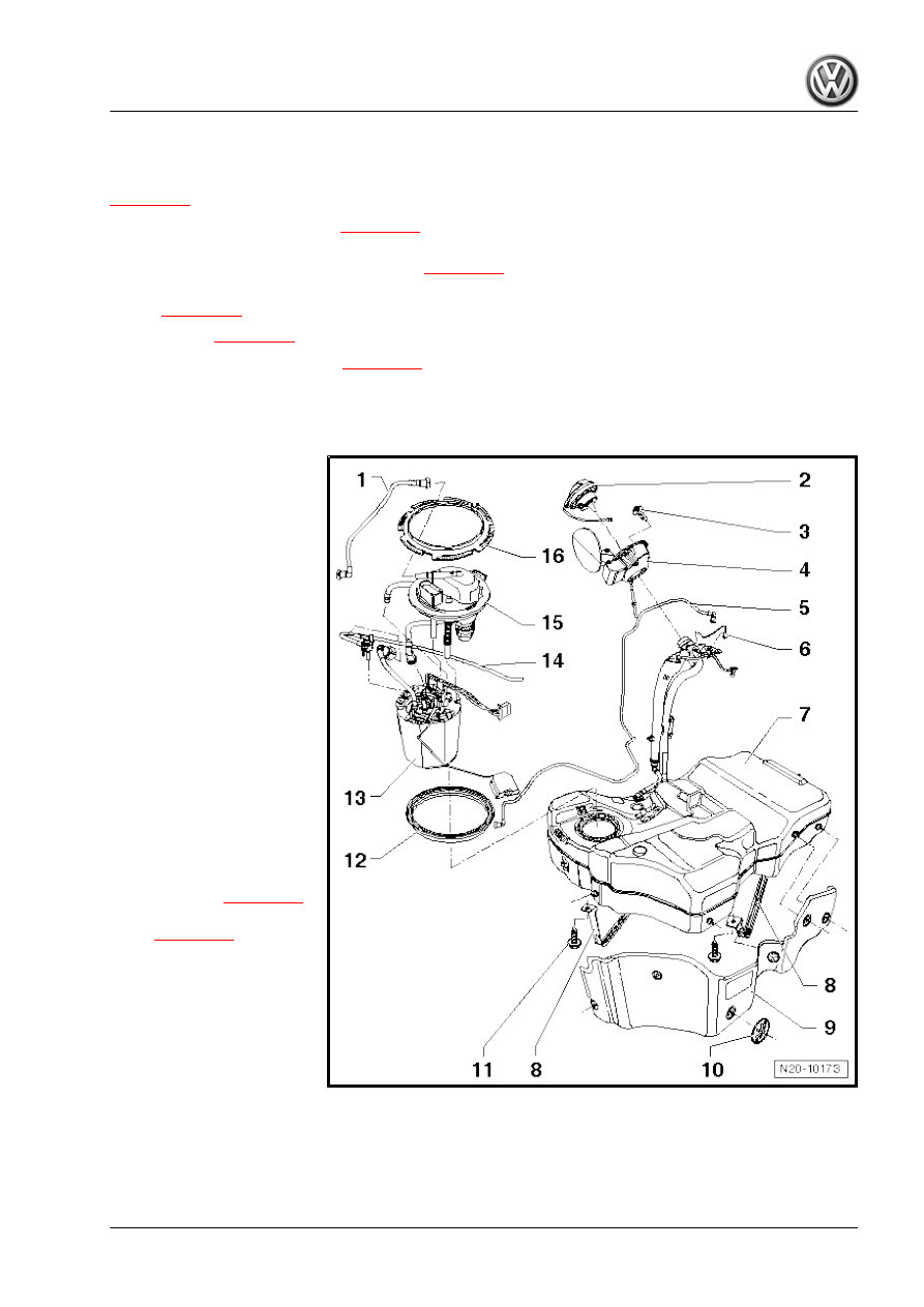
Assembly overview - fuel tank (engine codes BZB, CAWA, CAWB, CGYA,

CCZA, CCZB, CDAA, CDAB)

1 - Fuel line

❑ Ensure firm seating
❑ Clipped onto fuel tank

2 - Cap

❑ Renew if damaged

3 - Bolt, 1.5 Nm
4 - Tank flap unit

❑ With rubber cup.
❑ Removing and installing

⇒  General body repairs,

exterior; Rep. gr.  55 ;

Tank flap unit; Remov‐

ing and installing fuel

tank flap unit .

5 - Breather line

❑ Clipped onto fuel tank
❑ Ensure firm seating

6 - Earth connection

❑ Ensure firm seating

7 - Fuel

❑ Emptying 

⇒ page 283

❑ Removing and installing

⇒ page 287

8 - Securing strap
9 - Heat shield
10 - Clamping washer
11 - 25 Nm

❑ Renew
❑ To secure the securing

straps for the fuel tank,

only bolts with loose washers must be used. If different bolts are used, the securing straps might twist

during tightening. Bolts ⇒  ETKA (Electronic parts catalogue) .

12 - Seal

❑ Renew
❑ When installing, fit dry in fuel tank opening.

281

❑ Moisten with fuel only when installing flange.

13 - Fuel delivery unit

❑ Removing and installing 

⇒ page 326

❑ Checking fuel pump 

⇒ page 331

 .

❑ Removing and installing fuel gauge sender - G- 

⇒ page 330

❑ Clean strainer if soiled

14 - Suction-jet pump
15 - Flange with fuel filter

❑ With 6.2 bar pressure relief valve
❑ Removing and installing 

⇒ page 326

16 - Locking ring 110 Nm

❑ Ensure firm seating
❑ Remove and install using wrench - T10202- .

3.2

Assembly overview - fuel tank (engine codes CBFA, CCTA, CCTB)

1 - Fuel line

❑ Ensure firm seating

2 - Cap

❑ Renew if damaged

3 - Securing bolt
4 - Tank flap unit

❑ With rubber cup.
❑ Removing and installing

⇒  General body repairs,

exterior; Rep. gr.  55 ;

Tank flap unit; Remov‐

ing and installing fuel

tank flap unit .

5 - Breather line

❑ Clipped onto fuel tank
❑ Ensure firm seating

6 - Vacuum line

❑ Clipped onto fuel tank
❑ Ensure firm seating

7 - Earth connection

❑ To protective plate for

filler neck.

❑ Ensure firm seating

8 - Earth connection

❑ Ensure firm seating
❑ Ensure good contact to

body

9 - Clip
10 - Fuel

❑ Emptying 

⇒ page 283

❑ Removing and installing 

⇒ page 287

❑ When removing, support using engine and gearbox jack - V.A.G 1383 A- .

     Rep. gr.20 - Fuel supply system

11 - Securing straps
12 - Heat shield
13 - Clamping washer
14 - 25 Nm

❑ Renew
❑ To secure the securing straps for the fuel tank, only bolts with loose washers must be used. If different

bolts are used, the securing straps might twist during tightening. Bolts ⇒  ETKA (Electronic parts cata‐

logue) .

15 - Seal

❑ Renew
❑ When installing, fit dry in fuel tank opening.
❑ Moisten with fuel only when installing flange.

16 - Fuel delivery unit

❑ Removing and installing 

⇒ page 326

❑ Checking fuel pump 

⇒ page 331

 .

❑ Removing and installing fuel gauge sender - G- 

⇒ page 330

❑ Clean strainer if soiled

17 - Pop rivet
18 - Protective plate

❑ For filler neck.

19 - Suction-jet pump
20 - Flange with fuel filter

❑ With 6.2 bar pressure relief valve
❑ Removing and installing 

⇒ page 326

21 - Locking ring 110 Nm

❑ Ensure firm seating
❑ Remove and install using wrench - T10202- .

3.3

Emptying fuel tank

Special tools and workshop equipment required
♦ Fuel extractor - VAS 5190-

283

♦ Special wrench - T10202-

♦ Torque wrench (40 to 200 Nm) - V.A.G 1332-
– Note safety precautions before beginning work 

⇒ page 278

 .

Emptying fuel tank with fuel pump intact 

⇒ page 284

 .

Emptying fuel tank if more than 

3

/4 full 

⇒ page 286

Emptying fuel tank if less than 

3

/4 full 

⇒ page 286

3.3.1

Emptying fuel tank when fuel pump is

intact

Special tools and workshop equipment required
♦ Adapter for fuel extraction - VAS 5190 /3-
♦ Test instrument adapter/DSO (5-pin) - VAS 5565-
♦ Remote control - V.A.G 1348/3A-

WARNING

♦ Fuel supply line is pressurised. Wear protective goggles

and protective clothing to avoid injury and contact with the

skin. Wrap a cloth around the connection before loosening

hose connections. Then release pressure by carefully

pulling hose off connection.

♦ Connect fuel extractor - VAS 5190- earth cable to earth.

– Pull off supply line (metal coupling) -arrow- and catch escaping

fuel with a cloth.

Note

Press in securing ring to release the fuel lines.

     Rep. gr.20 - Fuel supply system

– Connect fuel extractor - VAS 5190- with adapter for fuel ex‐

tractor - VAS 5190 /3- to fuel supply line.

– Remove bench seat ⇒  General body repairs, interior; Rep. gr. 

72 ; Removing and installing bench seat .

– Remove cover -1- with fuel pump control unit - J538- -2- from

fuel delivery unit.

– Pull connector -A- off fuel delivery unit flange.

– Connect test instrument adapter/DSO (5-pin) - VAS 5565- to

connector and fuel delivery unit.

– Connect remote control - V.A.G 1348/3A- to adapter - VAS

5565- and to battery positive (+).

Note

This step serves only to have the fuel pump running when the

engine is stopped.

– Remove filler cap from fuel tank filler neck.
– Operate remote control - V.A.G 1348/3A- and shut-off tap on

fuel extractor - VAS 5190- until fuel tank is empty.

Caution

Do not allow the fuel pump run »dry«.

285

3.3.2

Emptying fuel tank if it is more than 

3

/4

full

Caution

Secure earth wire of fuel extractor - VAS 5190- to a bare metal

part of the body.

– Use insulating tape to mark the extraction hose -arrow- at a

distance of -a- = 990 mm from the end of the hose.

– Remove filler cap from fuel tank filler neck.
– Push extraction hose into fuel tank until marking on hose co‐

incides with filler neck.

Note

The shaft piece -1- is not used.

There is a flap on the lower end of the fuel filler neck in the fuel

tank which must not be damaged by the extraction hose.

Therefore, only push the hose in as far as the marking.

– Drain fuel tank as much as possible through fuel filler neck.
– Carefully pull out extraction hose.

Note

When no more fuel is extracted, the tank is emptied just

enough for the sender flange to be opened without danger.

The tank may be removed while containing remaining fuel.

Emptying the fuel tank completely 

⇒ page 286

 .

3.3.3

Emptying fuel tank if it is less than 

3

/4 full

– Remove bench seat ⇒  General body repairs, interior; Rep. gr. 

72 ; Removing and installing bench seat .

– Remove cover -1- with fuel pump control unit - J538- -2- from

fuel delivery unit.

WARNING

Fuel supply line is pressurised. Wear protective goggles and

protective clothing to avoid injury and contact with the skin.

Wrap  a  cloth  around  the  connection  before  loosening  hose

connections. Then release pressure by carefully pulling hose

off connection.

     Rep. gr.20 - Fuel supply system

– Release connector -1- and fuel line -2- and pull them off flange

-3-.

Note

Press in securing ring to release fuel line.

On vehicles with auxiliary heater, the connector and the fuel

line of the metering pump - V54- must also be disconnected.

– Open locking ring using key - T10202- .

Caution

Do not cant key - T10202- and press against locking ring firmly.

If the key slips off, the fuel delivery unit can be damaged.

– Lift sender flange.
– Insert extraction hose of fuel extractor - VAS 5190- as deeply

as possible into fuel tank and extract fuel.

If fuel tank needed only to be emptied, reinstall sender flange

⇒ page 326

 .

3.4

Removing and installing fuel tank

Special tools and workshop equipment required
♦ Torque wrench (5 to 50 Nm) - V.A.G 1331-

Remove fuel tank 

⇒ page 287

 .

Install fuel tank 

⇒ page 290

 .

3.4.1

Removing fuel tank

Note

The rear axle must be lowered to remove the fuel tank.

Note safety precautions before beginning work 

⇒ page 278

 .

Observe rules for cleanliness 

⇒ page 280

 .

Assembly overview - fuel tank 

⇒ page 281

 .

287

– If necessary, empty fuel tank using fuel extractor - VAS 5190-

⇒ page 283

 .

– Remove bench seat ⇒  General body repairs, interior; Rep. gr. 

72 ; Removing and installing bench seat .

– Remove cover -1- with fuel pump control unit - J538- -2- from

fuel delivery unit.

– Pull 5-pin connector -arrow- off flange.

Note

For vehicles with auxiliary heater the metering pump - V54- con‐

nector must be separated additionally.

– Remove rear right wheel.
– Remove rear right wheel housing liner ⇒  General body re‐

pairs, exterior; Rep. gr.  66 ; Wheel housing liner .

Engine codes BZB, CAWA, CAWB, CGYA, CCZA, CCZB, CDAA,

CDAB:
– Pull breather line and pressure retention valve -arrows- off ac‐

tivated charcoal filter.

Note

Grasp securing ring (grey) on pressure retention valve and pull

valve off upwards.

Engine codes CBFA, CCTA, CCTB:
– Pull breather lines and vacuum line -arrows- off activated

charcoal filter.

     Rep. gr.20 - Fuel supply system

All:
– Unclip wire from filler neck -arrows-.
– Unscrew tank flap unit securing bolt and remove tank flap unit

⇒  General body repairs, exterior; Rep. gr.  55 ; Tank flap unit;

Removing and installing tank flap unit .

– Unbolt filler neck from body -arrows-.

WARNING

Fuel supply line is pressurised. Wear protective goggles and

protective clothing to avoid injury and contact with the skin.

Wrap  a  cloth  around  the  connection  before  loosening  hose

connections. Then release pressure by carefully pulling hose

off connection.

– Separate breather line (white) -1- and fuel line (black) -2- at

connections.

Note

Press in securing ring to release fuel line.

Vehicles with auxiliary heater, the fuel line of the metering

pump - V54- must also be separated.

– Lower rear axle ⇒  Running gear, axles, steering; Rep. gr.  42 ;

Lowering rear axle .

Note

When lowering, ensure sufficient clearance to brake lines and

electrical wiring.

Take the help of another mechanic while unbolting and low‐

ering fuel tank.

– Hold fuel tank and unscrew bolts securing the tensioning

straps -arrows-.

– Remove tensioning straps.
– With the aid of a 2nd mechanic, lower the tank slowly and take

it out through the space between rear axle and body.

289

3.4.2

Installing fuel tank

– With the aid of a second mechanic, guide the filler neck in be‐

tween rear axle and body.

– Place fuel tank in mounting position and fit new securing bolts

-arrows-.

Note

To secure the securing straps for the fuel tank, only bolts with

loose washers must be used. If different bolts are used, the se‐

curing straps might twist during tightening. Bolts ⇒  ETKA (Elec‐

tronic parts catalogue) .

– Secure rear axle to body again ⇒  Running gear, axles, steer‐

ing; Rep. gr.  42 .

The remaining installation steps are carried out in the reverse se‐

quence of removal. During this procedure, observe the following:
♦ Install breather lines and fuel lines free of kinks.
♦ Ensure that line connections are tight.
♦ Check fuel tank/body earth connection on filler neck.
– Fill fuel tank with at least 5 litres of fuel.

WARNING

Risk of explosion of fuel tank. If a new or completely empty fuel

tank has been installed, it must be filled immediately with at

least 5 litres of fuel. The fuel pump must not be allowed to run

when the fuel tank is empty.

Specified torques:

Component

Specified torque

Tensioning straps to body

♦ Use new bolts!
♦ To secure the securing straps

for the fuel tank, only bolts with

loose washers must be used.

This will stop the securing

straps from being twisted out of

position when tightening the

bolts.

25 Nm

Filler neck to body

8 Nm + 90°

Subframe/rear axle to body

♦ Use new bolts!

⇒  Running gear, axles,

steering; Rep. gr.  42 ; Re‐

moving and installing rear

axle .

Fitting wheels

⇒  Running gear; Rep. gr. 

44 ; Specified torque for

mounting wheels

     Rep. gr.20 - Fuel supply system

4

Fuel tank (Golf, Scirocco)

Safety precautions when working on fuel supply system

⇒ page 278

 .

Comply with rules for cleanliness 

⇒ page 280

 .

Assembly overview - fuel tank (engine codes BZB, CAWA,

CAWB, CGYA, CCZA, CCZB, CDAA) 

⇒ page 291

 .

Assembly overview - fuel tank (engine codes CBFA, CCTA,

CCTB) 

⇒ page 293

 .

Draining fuel tank (engine codes BZB, CAWA, CAWB, CGYA,

CCZA, CCZB, CDAA) 

⇒ page 295

 .

Emptying fuel tank (engine codes CBFA, CCTA, CCTB)

⇒ page 299

 .

Removing and installing fuel tank 

⇒ page 301

 .

4.1

Assembly overview - fuel tank (engine codes BZB, CAWA, CAWB, CGYA,

CCZA, CCZB, CDAA)

1 - Securing bolt
2 - Cap

❑ Renew if damaged

3 - Earth connection

❑ Ensure firm seating

4 - 10 Nm
5 - Wiring guide
6 - 25 Nm

❑ Renew
❑ To secure the securing

straps for the fuel tank,

only bolts with loose

washers must be used.

If different bolts are

used, the securing

straps might twist during

tightening. Bolts ⇒  ET‐

KA (Electronic parts

catalogue) .

7 - Fuel

❑ When removing, sup‐

port using engine and

gearbox jack - V.A.G

1383 A- .

❑ Removing and installing

⇒ page 301

8 - Clamping washer
9 - Exhaust system retainer
10 - Securing strap

❑ Observe installation po‐

sition

11 - Heat shield
12 - Supply line

❑ To fuel rail

291

❑ Ensure firm seating

13 - Fuel filter

❑ Fitting position 

⇒ page 293

❑ Arrow points in direction of flow.

14 - Breather line

❑ Clipped onto side of fuel tank.
❑ Ensure firm seating

15 - Seal

❑ Renew
❑ When installing, fit dry in fuel tank opening.
❑ Moisten with fuel only when installing flange.

16 - Fuel delivery unit

❑ Removing and installing 

⇒ page 346

❑ Checking fuel pump 

⇒ page 350

 .

❑ Note installation position on fuel tank 

⇒ page 292

❑ With fuel gauge sender - G-
❑ Removing and installing fuel gauge sender - G- 

⇒ page 349

17 - Locking ring 110 Nm

❑ Ensure firm seating
❑ Remove and install using wrench - T10202- .

18 - Supply line

❑ black
❑ Clipped onto side of fuel tank.
❑ Ensure firm seating

19 - Return line

❑ blue
❑ Clipped onto side of fuel tank.
❑ Ensure firm seating

20 - Tank flap unit

❑ With rubber cup.
❑ Removing and installing ⇒  General body repairs, exterior; Rep. gr.  55 ; Tank flap unit; Removing and

installing fuel tank flap unit .

Installation position of fuel delivery unit
• Tab -2- on flange must be between lugs -1- and -3- on fuel

tank.

• -Arrow- points in direction of travel.

     Rep. gr.20 - Fuel supply system

Location of fuel filter
Pin -2- on filter housing must engage in notch of guide -1- on filter

bracket.

4.2

Assembly overview - fuel tank (engine codes CBFA, CCTA, CCTB)

1 - Securing bolt
2 - Earth connection

❑ Ensure firm seating

3 - Vacuum line

❑ To fuel system diagnos‐

tic pump - V144-

4 - 10 Nm
5 - Rivet
6 - Protective plate

❑ Riveted as standard to

bottom clamp

❑ When replacing fuel

tank, hold protective

plate against filler pipe

and rivet to clamp

7 - Cable bracket

❑ Clipped onto protective

plate

8 - 25 Nm

❑ Renew
❑ To secure the securing

straps for the fuel tank,

only bolts with loose

washers must be used.

If different bolts are

used, the securing

straps might twist during

tightening. Bolts ⇒  ET‐

KA (Electronic parts

catalogue) .

9 - Fuel

❑ When removing, sup‐

port using engine and

gearbox jack - V.A.G 1383 A- .

❑ Removing and installing 

⇒ page 301

10 - Clamping washer
11 - Exhaust system retainer
12 - Securing strap

❑ Observe installation position

293

13 - Heat shield
14 - Supply line

❑ To fuel rail
❑ Ensure firm seating

15 - Fuel filter

❑ Fitting position 

⇒ page 295

❑ Arrow points in direction of flow.

16 - Vacuum line

❑ From fuel system diagnostic pump - V144- to intake manifold.
❑ Clipped onto fuel tank
❑ Ensure firm seating

17 - Breather line

❑ From activated charcoal filter to activated charcoal filter solenoid valve 1 - N80-
❑ Clipped onto side of fuel tank.
❑ Ensure firm seating

18 - Seal

❑ Renew
❑ When installing, fit dry in fuel tank opening.
❑ Moisten with fuel only when installing flange.

19 - Fuel delivery unit

❑ Removing and installing 

⇒ page 346

❑ If fuel delivery unit was renewed, adapt engine control unit to fuel pump ⇒ Vehicle diagnostic tester

“Guided Functions”.

❑ Checking fuel pump 

⇒ page 350

 .

❑ Note installation position on fuel tank 

⇒ page 295

❑ With fuel gauge sender - G-
❑ Removing and installing fuel gauge sender - G- 

⇒ page 349

❑ Clean strainer if soiled

20 - Locking ring 110 Nm

❑ Ensure firm seating
❑ Remove and install using wrench - T10202- .

21 - Return line

❑ blue
❑ Clipped onto side of fuel tank.
❑ Ensure firm seating

22 - Cap

❑ Renew if damaged

23 - Tank flap unit

❑ With rubber cup.
❑ Removing and installing ⇒  General body repairs, exterior; Rep. gr.  55 ; Tank flap unit; Removing and

installing fuel tank flap unit .

24 - To activated charcoal filter
25 - Supply line

❑ black
❑ Clipped onto side of fuel tank.
❑ Ensure firm seating

     Rep. gr.20 - Fuel supply system

Installation position of fuel delivery unit
• Tab -2- on flange must be between lugs -1- and -3- on fuel

tank.

• -Arrow- points in direction of travel.

Location of fuel filter
Pin -2- on filter housing must engage in notch of guide -1- on filter

bracket.

4.3

Draining fuel tank (engine codes BZB,

CAWA, CAWB, CGYA, CCZA, CCZB,

CDAA)

Special tools and workshop equipment required
♦ Fuel extractor - VAS 5190-

♦ Special wrench - T10202-

♦ Torque wrench (40 to 200 Nm) - V.A.G 1332-

295

– Note safety precautions before beginning work 

⇒ page 278

 .

Emptying fuel tank with fuel pump intact 

⇒ page 296

 .

Emptying fuel tank if more than 

3

/4 full 

⇒ page 297

Emptying fuel tank if less than 

3

/4 full 

⇒ page 298

4.3.1

Emptying fuel tank when fuel pump is

intact

Special tools and workshop equipment required
♦ Adapter for fuel extraction - VAS 5190 /3-
♦ Test instrument adapter/DSO (5-pin) - VAS 5565-
♦ Remote control - V.A.G 1348/3A-

WARNING

♦ Fuel supply line is pressurised. Wear protective goggles

and protective clothing to avoid injury and contact with the

skin. Wrap a cloth around the connection before loosening

hose connections. Then release pressure by carefully

pulling hose off connection.

♦ Connect fuel extractor - VAS 5190- earth wire to vehicle

earth.

– Pull off supply line (metal coupling) -arrow- and catch escaping

fuel with a cloth.

Note

Press in securing ring to release the fuel lines.

– Connect fuel extractor - VAS 5190- with adapter for fuel ex‐

tractor - VAS 5190 /3- to fuel supply line.

– Remove bench seat ⇒  General body repairs, interior; Rep. gr. 

72 ; Removing and installing bench seat .

     Rep. gr.20 - Fuel supply system

– Remove cover -1- with fuel pump control unit - J538- -2- from

fuel delivery unit.

– Pull off connector -arrow-.

– Connect test instrument adapter/DSO (5-pin) - VAS 5565- to

connector and fuel delivery unit.

– Connect remote control - V.A.G 1348/3A- to test instrument

adapter/DSO (5-pin) - VAS 5565- and to battery positive (+).

Note

This step serves only to have the fuel pump running when the

engine is stopped.

– Remove filler cap from fuel tank filler neck.
– Operate remote control - V.A.G 1348/3A- and shut-off tap on

fuel extractor - VAS 5190- until fuel tank is empty.

Caution

Do not allow the fuel pump run »dry«.

4.3.2

Emptying fuel tank if it is more than 

3

/4

full

Caution

Secure earth wire of fuel extractor - VAS 5190- to a bare metal

part of the body.

297

– Remove cotter -2- from shaft -1- of fuel extractor - VAS 5190- .
– At a distance of -a- = 1180 mm from the end of the hose, mark

extraction hose with insulating tape -arrow-.

– Remove filler cap from fuel tank filler neck.
– Screw shaft end -1- of fuel extractor unit - VAS 5190- onto fuel

filler neck.

– Push extraction hose into fuel tank until marking on hose

-arrow- coincides with shaft end.

Note

A ball valve -2- is located at the bottom of the filler neck in the fuel

tank -1-; take care not to damage it with the extraction hose -3-.

Therefore push hose into filler neck only as far as marking

-arrow-.

– Drain fuel tank as much as possible through fuel filler neck.
– Carefully pull out extraction hose.

Note

When no more fuel is extracted, the tank is emptied just

enough for the sender flange to be opened without danger.

The tank may be removed while containing remaining fuel.

Emptying the fuel tank completely 

⇒ page 298

 .

4.3.3

Emptying fuel tank if it is less than 

3

/4 full

– Remove bench seat ⇒  General body repairs, interior; Rep. gr. 

72 ; Removing and installing bench seat .

     Rep. gr.20 - Fuel supply system

– Remove cover -1- with fuel pump control unit - J538- -2- from

fuel delivery unit.

WARNING

Fuel supply line is pressurised. Wear protective goggles and

protective clothing to avoid injury and contact with the skin.

Wrap  a  cloth  around  the  connection  before  loosening  hose

connections. Then release pressure by carefully pulling hose

off connection.

– Pull off connector -arrow-.

– Pull fuel lines -1- and -2- off the flange.

Note

Press in securing ring to release the fuel lines.

On vehicles with auxiliary heater, the connector and the fuel

line of the metering pump - V54- must also be disconnected.

– Open locking ring using key - T10202- and raise flange slightly.

Caution

Do not cant key - T10202- and press against locking ring firmly.

If the key slips off, the fuel delivery unit can be damaged.

– Insert extraction hose of fuel extractor - VAS 5190- as deeply

as possible into fuel tank and extract fuel.

If fuel tank needed only to be emptied, reinstall sender flange

⇒ page 346

 .

4.4

Emptying fuel tank (engine codes

CBFA, CCTA, CCTB)

Special tools and workshop equipment required

299

♦ Special wrench - T10202-

♦ Fuel extractor - VAS 5190-

♦ Torque wrench - V.A.G 1332-
– Note safety precautions before beginning work 

⇒ page 278

 .

Caution

Secure earth wire of fuel extractor - VAS 5190- to a bare metal

part of the body.

– Remove cotter -2- from shaft -1- of fuel extractor - VAS 5190- .
– At a distance of -a- = 1500 mm from the end of the hose, mark

extraction hose with insulating tape -arrow-.

– Remove filler cap from fuel tank filler neck.

     Rep. gr.20 - Fuel supply system

– Screw shaft end -1- of fuel extractor unit - VAS 5190- onto fuel

filler neck.

Note

On vehicles with plug-in connector, the shaft section of the fuel

extractor must be held accordingly.

– Insert suction hose in fuel tank until marking -arrow- (previ‐

ously made) is at the shaft section and extract fuel ⇒  Oper‐

ating instructions for fuel extractor - VAS 5190- .

Note

After approx. 120 cm a pressure point is noticeable. The non-

return flap in the fuel tank must be pushed open. Pull the hose

out slightly and push it in with a slight jerk.

The fuel tank is emptied almost completely in this way.

Proceed in same manner when pulling hose out.

4.5

Removing and installing fuel tank

Special tools and workshop equipment required
♦ Torque wrench (5 to 50 Nm) - V.A.G 1331-

♦ Engine and gearbox jack - V.A.G 1383 A-

Removing fuel tank
– Note safety precautions before beginning work 

⇒ page 278

 .

– Observe rules for cleanliness 

⇒ page 280

 .

– If necessary, empty fuel tank using fuel extractor - VAS 5190- :

Engine codes BZB, CAWA, CAWB, CGYA, CCZA, CCZB,

CDAA 

⇒ page 295

 .

301

Engine codes CBFA, CCTA, CCTB 

⇒ page 299

 .

– Remove bench seat ⇒  General body repairs, interior; Rep. gr. 

72 ; Removing and installing bench seat .

– Remove cover -1- with fuel pump control unit - J538- -2- from

fuel delivery unit.

– Pull off connector -arrow-.

Note

For vehicles with auxiliary heater the metering pump - V54- con‐

nector must be separated additionally.

– Remove rear right wheel.
– Remove rear right wheel housing liner ⇒  General body re‐

pairs, exterior; Rep. gr.  66 ; Wheel housing liner .

– Unscrew tank flap unit securing bolt and remove tank flap unit

⇒  General body repairs, exterior; Rep. gr.  55 ; Tank flap unit .

Engine codes CAWB, CCZA, CCZB, CDAA:
– Unbolt filler neck from body -1-.
– Unclip electrical wiring -2- from filler neck.

     Rep. gr.20 - Fuel supply system

Engine codes CBFA, CCTA:
– Disconnect hoses -1- and -2-.
– Unbolt filler neck from body -arrows-.
– Unclip electrical wiring from filler neck.
All:
– Remove centre and rear silencers.
– Remove heat shields from middle and rear silencers.

WARNING

Fuel supply line is pressurised. Wear protective goggles and

protective clothing to avoid injury and contact with the skin.

Wrap  a  cloth  around  the  connection  before  loosening  hose

connections. Then release pressure by carefully pulling hose

off connection.

Note

Press in securing ring to release the fuel lines.

– Disconnect breather line -1- (white) and fuel line -2- (black) at

connecting point.

Note

On vehicles for USA/Canada, the vacuum line for the fuel sys‐

tem diagnostic pump - V144- must be separated in addition.

Vehicles with auxiliary heater, the fuel line of the metering

pump - V54- must also be separated.

303

– Unscrew securing strap and securing bolts. When doing this,

support fuel tank with engine and gearbox jack - V.A.G 1383

A- .

– Lower fuel tank.
Installing fuel tank:
Install in reverse order of removal. During this procedure, observe

the following:
Specified torques: Assembly overview - fuel tank.

Engine codes BZB, CAWA, CAWB, CGYA, CCZA, CCZB,

CDAA 

⇒ page 291

 .

Engine codes CBFA, CCTA, CCTB 

⇒ page 293

 .

♦ To secure the securing straps for the fuel tank, only bolts with

loose washers must be used. If different bolts are used, the

securing straps might twist during tightening.

♦ Install breather lines and fuel lines free of kinks.
♦ Do not interchange supply line and return line (return line blue

or with blue marking, supply line black).

♦ Ensure wiring/line connections are secured properly by pulling

back.

♦ Check earth connection on fuel tank and body to filler neck.
– Fill fuel tank with at least 5 litres of fuel.

WARNING

Risk of explosion of fuel tank. If a new or completely empty fuel

tank has been installed, it must be filled immediately with at

least 5 litres of fuel. The fuel pump must not be allowed to run

when the fuel tank is empty.

     Rep. gr.20 - Fuel supply system

5

Fuel tank (Tiguan)

Assembly overview - fuel tank 

⇒ page 305

 .

Drain fuel tank 

⇒ page 307

 .

Removing and installing fuel tank 

⇒ page 310

 .

5.1

Assembly overview - fuel tank

1 - Cap

❑ Renew if damaged

2 - Securing bolt
3 - Earth connection

❑ Ensure firm seating

4 - Breather line

❑ To activated charcoal fil‐

ter

❑ Ensure firm seating

5 - Locking ring 110 Nm

❑ Ensure firm seating
❑ Remove and install us‐

ing fuel tank sender unit

tool - 3087- .

6 - Fuel delivery unit

❑ Removing and installing

⇒ page 366

❑ Checking fuel pump

⇒ page 375

 .

❑ Note installation posi‐

tion on fuel tank

⇒ page 306

❑ With fuel gauge sender

- G-

❑ Removing and installing

fuel gauge sender - G-

⇒ page 370

❑ Clean strainer if soiled

7 - Supply line

❑ black
❑ Clipped onto side of fuel

tank.

❑ Ensure firm seating

8 - Flange on left side

❑ With fuel gauge sender 2 - G169- .
❑ With suction-jet pump
❑ With pressure limiting valve
❑ With fuel filter
❑ Removing and installing 

⇒ page 373

305

9 - 3.5 Nm
10 - Bracket for fuel pump control unit - J538-
11 - Fuel pump control unit - J538-

❑ Removing and installing 

⇒ page 374

12 - Seal

❑ Renew if damaged
❑ When installing, fit dry in fuel tank opening.
❑ Moisten with fuel only when installing flange.

13 - Fuel

❑ When removing, support using engine and gearbox jack - V.A.G 1383 A- .
❑ Removing and installing 

⇒ page 310

14 - 25 Nm

❑ Renew
❑ To secure the securing straps for the fuel tank, only bolts with loose washers must be used. If different

bolts are used, the securing straps might twist during tightening. Bolts ⇒  ETKA (Electronic parts cata‐

logue) .

15 - Securing strap

❑ Observe installation position

16 - 25 Nm

❑ Renew

17 - Clamping washer
18 - Heat shield
19 - Breather line

❑ Clipped onto side of fuel tank.
❑ Ensure firm seating

20 - Breather line

❑ Ensure firm seating

21 - 8 Nm + 

1

/4 turn (90°) further

❑ Renew

22 - Tank flap unit

❑ With rubber cup.
❑ Removing and installing ⇒  General body repairs, exterior; Rep. gr.  55 ; Tank flap unit; Removing and

installing fuel tank flap unit .

Installation position of flange for fuel delivery unit and fuel gauge

sender 2 - G169-
Fuel delivery unit -3-:
The lug -1- points in direction of travel.
Fuel gauge sender 2 - G169- -2-:
The lug -1- points in direction of travel.

Note

The arrows on the locking rings may be disregarded.

     Rep. gr.20 - Fuel supply system

5.2

Emptying fuel tank

Special tools and workshop equipment required
♦ Fuel extractor - VAS 5190-

♦ Fuel tank sender unit tool - 3087-

♦ Torque wrench (40 to 200 Nm) - V.A.G 1332-
– Note safety precautions before beginning work 

⇒ page 278

 .

Emptying fuel tank with fuel pump intact 

⇒ page 307

 .

Emptying fuel tank if more than 

3

/4 full 

⇒ page 309

Emptying fuel tank if less than 

3

/4 full 

⇒ page 309

5.2.1

Emptying fuel tank when fuel pump is

intact

Special tools and workshop equipment required
♦ Adapter for fuel extraction - VAS 5190 /3-
♦ Test instrument adapter/DSO (5-pin) - VAS 5565-
♦ Remote control - V.A.G 1348/3A-

WARNING

♦ Fuel supply line is pressurised. Wear protective goggles

and protective clothing to avoid injury and contact with the

skin. Wrap a cloth around the connection before loosening

hose connections. Then release pressure by carefully

pulling hose off connection.

♦ Connect fuel extractor - VAS 5190- earth wire to vehicle

earth.

307

– Pull off supply line (metal coupling) -arrow- and catch escaping

fuel with a cloth.

Note

Press in securing ring to release the fuel lines.

– Connect fuel extractor - VAS 5190- with adapter for fuel ex‐

tractor - VAS 5190 /3- to fuel supply line.

– Remove bench seat ⇒  General body repairs, interior; Rep. gr. 

72 ; Removing and installing bench seat .

– Remove cover from fuel delivery unit.

– Pull 5-pin connector -1- off right flange (in direction of travel).

– Connect test instrument adapter/DSO (5-pin) - VAS 5565- to

connector and fuel delivery unit.

– Connect remote control - V.A.G 1348/3A- to test instrument

adapter/DSO (5-pin) - VAS 5565- and to battery positive (+).

Note

This step serves only to have the fuel pump running when the

engine is stopped.

– Remove filler cap from fuel tank filler neck.
– Operate remote control - V.A.G 1348/3A- and shut-off tap on

fuel extractor - VAS 5190- until fuel tank is empty.

Caution

Do not allow the fuel pump run »dry«.

     Rep. gr.20 - Fuel supply system

5.2.2

Emptying fuel tank if it is more than 

3

/4

full

Caution

Secure earth wire of fuel extractor - VAS 5190- to a bare metal

part of the body.

– Use insulating tape to mark the extraction hose -arrow- at a

distance of -a- = 1200 mm from the end of the hose.

– Remove filler cap from fuel tank filler neck.
– Push extraction hose into fuel tank until marking on hose co‐

incides with filler neck.

Note

The shaft piece -1- is not used.

There is a flap on the lower end of the fuel filler neck in the fuel

tank which must not be damaged by the extraction hose.

Therefore, only push the hose in as far as the marking.

– Drain fuel tank as much as possible through fuel filler neck.
– Carefully pull out extraction hose.

Note

When no more fuel is extracted, the tank is emptied just

enough for the sender flange to be opened without danger.

The tank may be removed while containing remaining fuel.

Emptying the fuel tank completely 

⇒ page 309

 .

5.2.3

Emptying fuel tank if it is less than 

3

/4 full

– Remove bench seat ⇒  General body repairs, interior; Rep. gr. 

72 ; Removing and installing bench seat .

– Remove cover from fuel delivery unit.

WARNING

Fuel supply line is pressurised. Wear protective goggles and

protective clothing to avoid injury and contact with the skin.

Wrap  a  cloth  around  the  connection  before  loosening  hose

connections. Then release pressure by carefully pulling hose

off connection.

– Pull connector and fuel lines off flange.

Note

Press buttons on hose couplings to do this.

309

– Open locking ring using fuel tank sender wrench - 3087- .
– Raise fuel delivery unit.
– Insert extraction hose of fuel extractor - VAS 5190- as deeply

as possible into fuel tank and extract fuel.

If fuel tank needed only to be emptied, install fuel delivery unit

again 

⇒ page 366

 .

5.3

Removing and installing fuel tank

Special tools and workshop equipment required
♦ Torque wrench (5 to 50 Nm) - V.A.G 1331-

♦ Engine and gearbox jack - V.A.G 1383 A-

Removing
– Note safety precautions before beginning work 

⇒ page 278

 .

– First check whether a coded radio is fitted. If so, obtain anti-

theft code.

– With the ignition switched off, disconnect battery earth strap.
– Unscrew securing bolts and remove tank flap unit.
– Drain fuel tank and clean fuel filler neck and surrounding area.
– Remove bench seat ⇒  General body repairs, interior; Rep. gr. 

72 ; Removing and installing bench seat .

– Remove cover from fuel delivery unit.

     Rep. gr.20 - Fuel supply system

– Pull connector -1- and fuel line -2- off right flange (in direction

of travel).

– Release connector -arrow- on fuel pump control unit - J538-

using assembly tool - T10118- and pull it off.

– Pull connector -1- off left flange (in direction of travel).
– Remove rear exhaust system with centre and rear silencers.

– First, undo bolt -1- and then bolts -2…3- and remove pendu‐

lum support.

– Remove propshaft ⇒  Propshaft and rear final drive; Rep. gr. 

39 ; Removing and installing propshaft .

WARNING

Fuel supply lines are under pressure! Wear eye protection and

gloves to avoid injuries and skin contact. Wrap a cloth around

the connection before loosening hose connections. Then re‐

lease pressure by carefully pulling hose off connection.

311

– Disconnect fuel line -1- (black) and breather line -2- (white) at

connecting point.

– If an auxiliary heater is fitted, also separate fuel line -3-.

Note

Press in securing ring to release the fuel lines.

– Remove rear right wheel.
– Remove rear right wheel housing liner ⇒  General body re‐

pairs, exterior; Rep. gr.  66 ; Wheel housing liner .

Engine codes BZB, CAWA, CAWB, CGYA:
– Disconnect breather lines -1- from activated charcoal filter and

fuel filler neck -3-.

– Unclip wheel sensor wire -2- from retainer on filler neck.

Engine codes CBFA, CCTA, CCTB:
– Pull breather lines and vacuum line -arrows- off activated

charcoal filter.

– Unclip wheel sensor wire -arrows- from retainer on filler neck.
All:
– Remove tank flap and fuel tank filler neck cap.
– Disconnect earth cable at fuel filler neck.

     Rep. gr.20 - Fuel supply system


Content      ..     8      9      10      11     ..