Volkswagen Golf / Golf GTI / Jetta. Manual - part 57
 

  Index      Volkswagen     Volkswagen Golf / Golf GTI / Jetta - service repair manual 1999-2005 year


Search            copyright infringement  


Content   ..  55  56  57  58   ..


Volkswagen Golf / Golf GTI / Jetta. Manual - part 57


17-21


Note:  

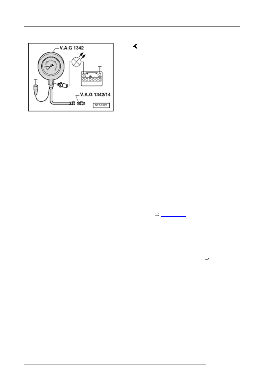
Observe installation position of 
adapter: The tapered connecting 
socket of the adapter is screwed to 
the pressure hose of the tester.
 

If the LED lights up:  

If the LED does not light up:  

-  Remove Oil pressure switch -F1- 

and screw into tester. 

-  Screw tester VAG 1342 with 

adapter VAG 1342/14 into oil filter 
bracket instead of oil pressure 
switch. 

-  Connect brown wire of tester to 

Ground (-). 

-  Connect diode test lamp VAG 

1527 B to battery positive (+) and 
oil pressure switch using adapter 
cables from VAG 1594 A. 

   LED must not light up. 

-  Replace Oil pressure switch -F1- 


Page 17-9

 , item - 2 -. 

-  Start engine and run at idling 

speed. At 1.2...1.6 bar LED must 
light up; otherwise replace Oil 
pressure switch -F1- 


Page 17-

9

 , item - 2 -. 

Lubrication system components, servicing

17-22


   Checking oil pressure  


-  Check oil pressure at different revolutions: 


   2,000 rpm: 3.0...5.5 bar 


   above 2,000 rpm: maximum 7.0 bar.  


   If the specifications are not attained:  


-  Repair mechanical damage, e.g. bearing 

damage. 


   At higher engine speeds oil pressure must not 

exceed 7.0 bar. 


   If the specification is exceeded:  


-  Check oil galleries. 


-  Replace oil pump if necessary 


Page 17-12

 , 

Disassembling and assembling oil pump. 

Lubrication system components, servicing

19-1


Cooling system components, 
servicing 


CAUTION!


When performing repair work, especially due 
to the confined conditions in the engine 
compartment, pay attention to the following:


Route all types of lines (e.g. for fuel, 
hydraulics, EVAP system, coolant, 
refrigerant, brake fluid and vacuum) as well 
as electrical wiring so that the original 
positions are restored.


Make sure sufficient clearance to all moving 
or hot components.


Note:  


 When the engine is warm the cooling system is 

under pressure. If necessary release pressure 
before commencing repair work.


 Hoses are secured with spring-type clips. In 

cases of repair only use spring-type clips.


 Assembly tool VAS 5024 or hose clip pliers 

VAG 1921 are recommended for installing 
spring-type clips.
 

 When installing coolant hoses route stress

so that they do not come into contact with other 
components (observe markings on coolant 
connection and hose).
 

Cooling system components, servicing

19-2


   Perform cooling system leakage test with 

cooling system tester VAG 1274 and 
adapters VAG 1274/8 and VAG 1274/9.  


   Parts of cooling system, body side 


Page 

19-3

 .  


   Parts of cooling system, engine side 


Page 19-6

 .  


   Coolant hose connection diagram 


Page 

19-11


   Disassembling and assembling coolant 

thermostat housing 

 Page  


Page 19-

13

 .  


   Draining and filling coolant 


Page 19-15

 .  


   Coolant mixing ratios 


Page 19-15

 , 

Draining and filling coolant.  

Cooling system components, servicing


Content   ..  55  56  57  58   ..