Volkswagen Golf / Golf GTI / Jetta. Manual - part 56
 

  Index      Volkswagen     Volkswagen Golf / Golf GTI / Jetta - service repair manual 1999-2005 year


Search            copyright infringement  


Content   ..  54  55  56  57   ..


Volkswagen Golf / Golf GTI / Jetta. Manual - part 56


17-17


Note:  

The sealing compound bead must 
not be thicker, otherwise excess 
sealing compound will enter the oil 
pan and may block the oil suction 
pipe strainer.
 

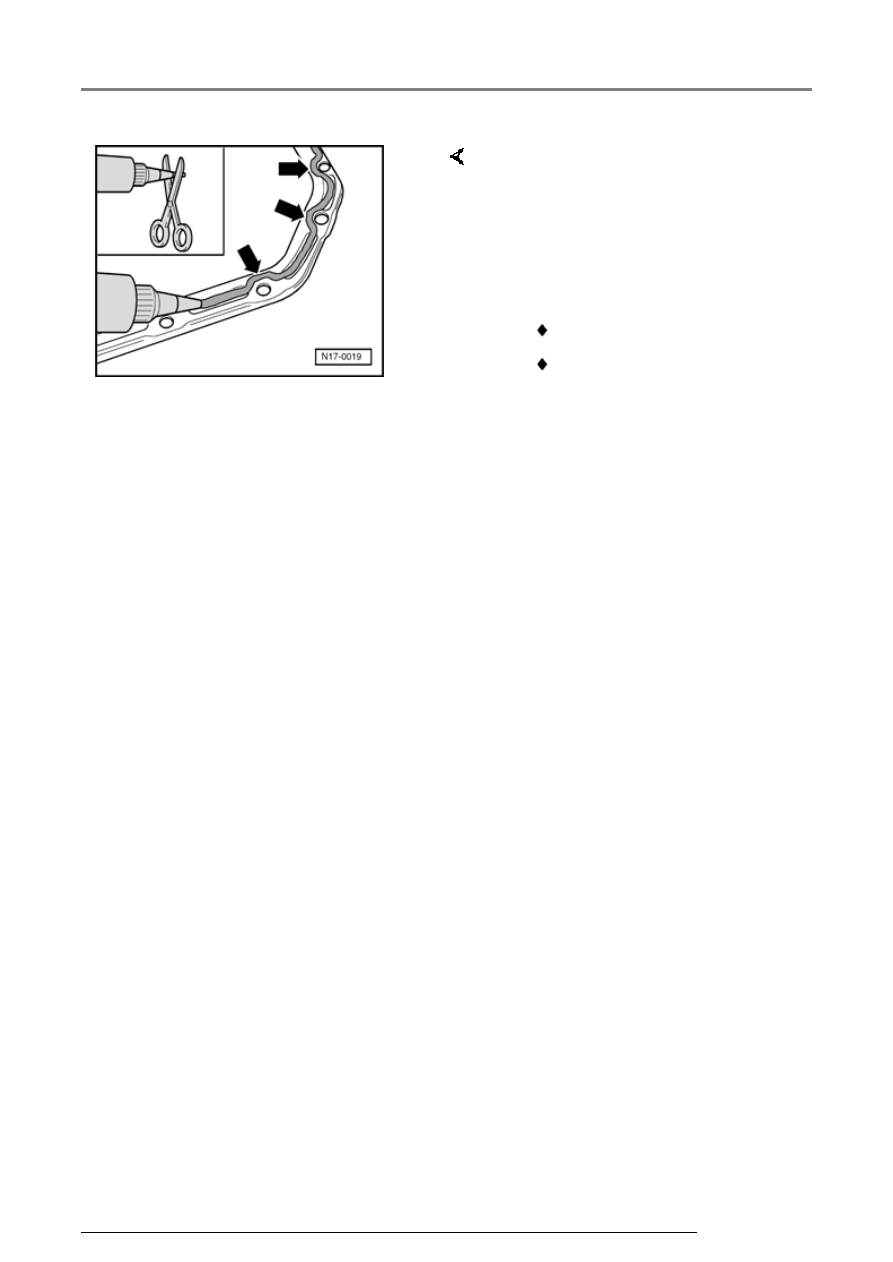
-  Cut off tube nozzle at front 

marking (nozzle approx. 3 mm 
diameter). 

-  Apply silicone sealing compound, 

as shown, to clean oil pan sealing 
surface. Sealing compound bead 
must be: 


 2...3 mm thick, 


 and run on inside of bolt holes 

(arrows). 

Lubrication system components, servicing

17-18


Note:  

The sealing compound must be 
allowed to cure for approx. 30 
minutes after installing the oil pan. 
After this time the engine may be 
filled with engine oil.
 

The rest of the assembly is basically 
in reverse order to the disassembling 
sequence.  

-  Apply silicone sealing compound 

bead as illustrated to clean 
sealing surface of oil pan. 

-  Install oil pan immediately and 

tighten all pan bolts lightly. 

-  Tighten oil pan bolts to 12 Nm. 

-  Tighten bolts for 

pan/transmissionto 45 Nm. 

-  Tighten bracket for secondary air 

pump motor: 

   Securing bolts to oil pan: 8 Nm 

   Securing bolts to cylinder block: 

20 Nm 

Lubrication system components, servicing

17-19


Oil 
pressure 
and oil 
pressure 
switch, 
checking 


Special tools 
and 
equipment 
 

 VAG 1342 

Oil 
pressure 
tester 

 VAG 

1342/14 
Adapter 

 VAG 1527 

B Diode 
test lamp 

 VAG 1594 

A Adapter 
set 

Lubrication system components, servicing

17-20


   Test conditions  


 Engine oil level OK, checking 


Page 

17-8

 , 


Fig. 2

 . 


 Engine oil temperature at least 80  C 

(coolant fan must have run once). 


 Selector lever must be in position "P" or 

"N" on vehicles with an automatic 
transmission. 


   Note:  


   Functional check and servicing the optical 

and acoustic oil pressure warning: 


 Electrical Wiring Diagrams, 

Troubleshooting & Component Locations 


   Checking oil pressure switch  


-  Remove center, left and right insulation 

trays: 


Repair Manual, Body Exterior, Repair 

Group 50


-  Remove front bumper: 


Repair Manual, Body Exterior, Repair 

Group 63


-  Bring lock carrier into service position: 


Repair Manual, Body Exterior, Repair 

Group 50


Lubrication system components, servicing


Content   ..  54  55  56  57   ..