Volkswagen 01M Transmission. Manual - part 108


  Index      Volkswagen     Volkswagen 01M Transmission - service manual 2001 year


Search            copyright infringement  


Content   ..  106  107  108  109   ..


Volkswagen 01M Transmission. Manual - part 108


550

552

553

554

555

556

557

558

559

560

556

554

551

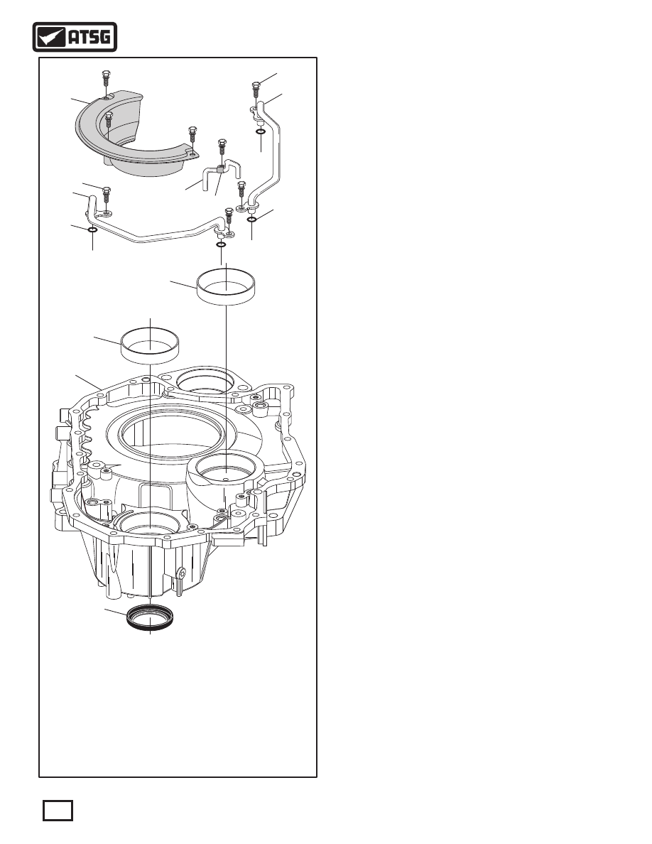
 550  CONVERTER COVER ASSEMBLY.
 551  RIGHT HAND AXLE SEAL.
 552  TAPERED ROLLER BEARING RACE  (FINAL DRIVE).
 553  TAPERED ROLLER BEARING RACE  (TRANSFER/PINION SHAFT).
 554  OIL PIPE "O" RING SEALS  (4 REQUIRED).
 555  LOWER OIL PIPE ASSEMBLY.
 556  RETAINING BOLTS WITH WASHER, 11MM LONG (8 REQUIRED).
 557  FINAL DRIVE OIL BAFFLE.
 558  CENTER OIL PIPE.
 559  CENTER OIL PIPE RETAINING BRACKET.
 560  UPPER OIL PIPE ASSEMBLY.

COMPONENT REBUILD

CONVERTER COVER ASSEMBLY

Figure 89

   1. Disassemble the converter cover parts using
       Figure 89 as a guide.
   2. Clean all converter cover parts thoroughly and
       dry with compressed air.
   3. Inspect all converter cover parts thoroughly and
       replace as necessary.

   4. Install new "O" ring seals on the 2 large diameter
       oil pipes, as shown in Figure 89, and lube with a
       small amount of Trans-Jel®.
   5. Install the two large diameter pipes, as shown in
       Figure 89,and torque the four retaining bolts to 
       8 N·m (70 in.lb.).
   6. Install the center oil pipe by pressing into place,
       as shown in Figure 89, and torque the retaining
       bolt to 8 N·m (70 in.lb.).
   7. Install the final drive oil baffle, as shown in
       Figure 89, and torque bolts to 8 N·m (70 in.lb.).
   8. Install new right hand axle seal, as shown in
       Figure 89, using the proper seal driver.
   9. Lube the inside diameter of the axle seal with a
       small amount of Trans-Jel.
 10. Install new tapered roller bearing races as
       necessary.
 11. Set the completed converter cover assembly aside
       for final transaxle assembly.

Component Rebuild

Continued on Page 63

62

Copyright © 2010 ATSG

AUTOMATIC TRANSMISSION SERVICE GROUP

Technical Service Information

WARNING: At time of this printing, there are not 
any  new  "hard  parts"  available  from  the 
manufacturer for this unit. The only source will be 
used aftermarket suppliers.

WWW.ALL-TRANS.BY

7

4051 - 1 - 1

03C2T02168

Z

0

300  035H

09G

1004

   1. Clean all transaxle case parts thoroughly and dry
       with compressed air.
   2. Inspect all case parts thoroughly and replace as
       necessary.

   3. Inspect the steel sleeve in the rear of case very
       closely, as shown in Figure 90.
       Note: This sleeve contains sealing rings for the
       K2 clutch and sleeve is prone to "spinning" on
       the case, creating cross-leaks.
       There is a replacement sleeve available from
       Sonnax® under part number 15759-01K with
       improved retention and includes installation
       instructions for 09G, 09K, 09M.
   4. Install two new sealing rings into the grooves in
       the steel sleeve at rear of case (See Figure 90)
       and lube with small amount of Trans-Jel®.
   5. Install tapered roller bearing and roller bearing
       race as necessary, as shown in Figure 91.
       Note: Shims under the tapered roller bearing
       and the roller bearing race are used to set the
       pre-load for final drive and transfer/pinion
       gear shaft, which should be 4 to 6 inch pounds
       of rotating torque.
   6. Install new inner and outer "O" ring seals into
       B2 clutch piston grooves, as shown in Figure 92,
       and lube with small amount of Trans-Jel.

Figure 91

561

562

563

564

 561  TAPERED ROLLER BEARING  (FINAL DRIVE).
 562  ROLLER BEARING SHIM (SETS FINAL DRIVE PRE-LOAD).
 563  TAPERED ROLLER BEARING RACE (TRANSFER/PINION GEAR).
 564  BEARING RACE SHIM  (SETS TRANSFER/PINION PRE-LOAD).

Figure 90

COMPONENT REBUILD (CONT'D)

TRANSAXLE CASE ASSEMBLY

WARNING: At time of this printing, there are not 
any  new  "hard  parts"  available  from  the 
manufacturer for this unit. The only source will be 
used aftermarket suppliers.

482

483

484

Figure 92

 482  B2 CLUTCH APPLY PISTON.
 483  B2 CLUTCH APPLY PISTON INNER "O" RING SEAL.
 484  B2 CLUTCH APPLY PISTON OUTER "O" RING SEAL.

Continued on Page 64

63

Copyright © 2010 ATSG

Copyright © 2010 ATSG

Copyright © 2010 ATSG

AUTOMATIC TRANSMISSION SERVICE GROUP

Technical Service Information

WWW.ALL-TRANS.BY

513

Copyright © 2010 ATSG

7

4051 - 1 - 1

03C2T02168

Z

0

300  035H

09G

1004

482

 482  B2 CLUTCH APPLY PISTON.

Figure 93

   7. Lubricate the "O" ring seal surfaces of the case
       with a liberal amount of Trans-Jel®.
   8. Install the B2 clutch apply piston into the case,
       as shown in Figure 93.
       Note: This piston must be oriented properly as
       it installs in one direction only. The piston tab
       without spring seal must be installed into slot
       as shown in Figure 93.
   9. Use extra care installing this piston as the seal is
       easily damaged during the install process.
 10. Install the B2 clutch return spring assembly, as
       shown in Figure 94.
       Note: The return spring assembly must also be
       oriented properly, as shown in Figure 94.
       Ensure that each of the springs are properly
       seated on the tabs and over the centering cones.

COMPONENT REBUILD (CONT'D)

TRANSAXLE CASE ASSEMBLY (CONT'D)

Figure 94

Component Rebuild

Continued on Page 65

64

Copyright © 2010 ATSG

AUTOMATIC TRANSMISSION SERVICE GROUP

Technical Service Information

7

4051 - 1 - 1

03C2T02168

Z

0

300  035H

09G

1004

480

481

 480  B2 CLUTCH RETURN SPRING SNAP RING  (.048" THICKNESS).
 481  B2 CLUTCH APPLY PISTON RETURN SPRING ASSEMBLY.
 513  NUMBER 11 THRUST BEARING RACE.

This tab "must"

be installed in

this slot.

This tab "must"

be installed in

this slot.

 11. Compress the return spring and install the snap
       ring, as shown in Figure 94, and ensure it is fully
       seated in the case groove.
       Note: This snap ring is .048" thick and the
       opening goes toward the transfer gear.
 12. Install the number 11 thrust bearing into rear of
       case, as shown in Figure 94, and retain with a
       small amount of Trans-Jel®.
       Note: Ensure tabs are engaged in case slots.
 

13. Set transaxle case aside for the final assembly

       process.

WWW.ALL-TRANS.BY

OIL PUMP ASSEMBLY EXPLODED VIEW

58

59

60

61

62

63

63

64

65

66

67

68

69

70

71

72

73

 58  OIL PUMP CONVERTER HUB SEAL.
 59  OIL PUMP CONVERTER HUB BUSHING.
 60  OIL PUMP TO CONVERTER COVER "O" RING SEAL .
 61  OIL PUMP TO CONVERTER COVER SEAL .
 62  OIL PUMP BODY.
 63  OIL PUMP HOLLOW ALIGNMENT DOWELS  (2 REQUIRED).
 64  OIL PUMP OUTER GEAR, GEROTOR STYLE.
 65  OIL PUMP INNER GEAR, GEROTOR STYLE.
 66  OIL PUMP COVER AND STATOR SHAFT ASSEMBLY.

 67  PUMP COVER RETAINING BOLTS & WASHERS (8 REQUIRED).
 68  OIL PUMP COVER, BUTT-CUT, SEAL RINGS  (2 REQUIRED).
 69  B-1 CLUTCH PISTON OUTER "O" RING SEAL.
 70  B-1 CLUTCH PISTON.
 71  B-1 CLUTCH PISTON INNER "O" RING SEAL.
 72  OIL PUMP COVER CAGED NEEDLE BEARING.
 73  NUMBER 1 THRUST WASHER.

65

Copyright © 2010 ATSG

AUTOMATIC TRANSMISSION SERVICE GROUP

Technical Service Information

COMPONENT REBUILD (CONT'D)

OIL PUMP ASSEMBLY

   1. Disassemble the oil pump using Figure 95 as a
       guide.
   2. Clean all oil pump assembly parts thoroughly
       and dry with compressed air.
   3. Inspect all oil pump assembly parts thoroughly
       and replace as necessary.

Figure 95

WARNING: At time of this printing, there are not 
any  new  "hard  parts"  available  from  the 
manufacturer for this unit. The only source will be 
used aftermarket suppliers.

Continued on Page 66

WWW.ALL-TRANS.BY


Content   ..  106  107  108  109   ..