Volkswagen 01M Transmission. Manual - part 109
69
70
71
69 B1 CLUTCH APPLY PISTON OUTER "O" RING SEAL.
70 B1 CLUTCH APPLY PISTON.
71 B1 CLUTCH APPLY PISTON INNER "O" RING SEAL.
32
6 1
C
A
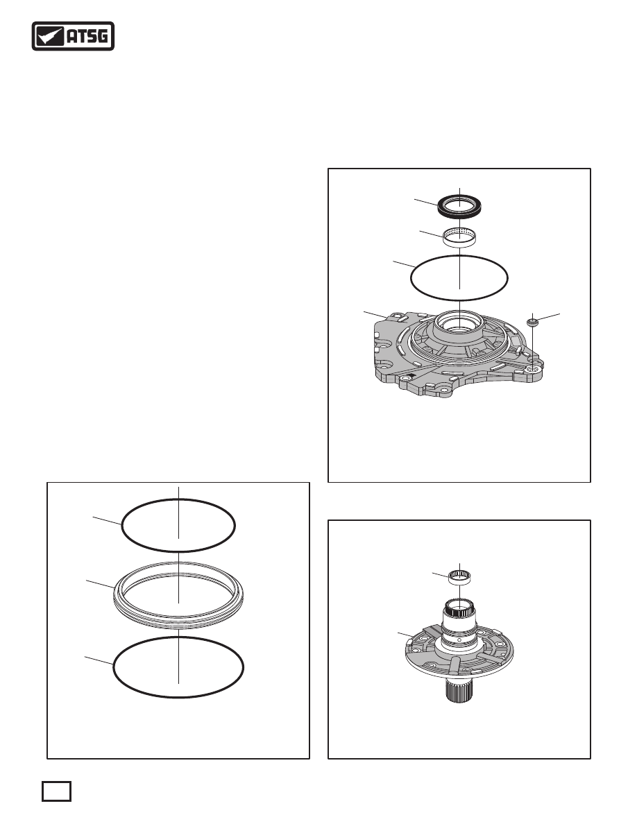
58
59
60
61
62
58 OIL PUMP CONVERTER HUB SEAL.
59 OIL PUMP CONVERTER HUB BUSHING.
60 OIL PUMP TO CONVERTER COVER "O" RING SEAL.
61 OIL PUMP TO CONVERTER COVER SEAL ASSEMBLY.
62 OIL PUMP BODY.
66
72
66 OIL PUMP COVER AND STATOR SHAFT ASSEMBLY.
72 OIL PUMP COVER CAGED NEEDLE BEARING.
COMPONENT REBUILD (CONT'D)
OIL PUMP ASSEMBLY (CONT'D)
4. Install new "O" ring seals into the grooves on
B1 clutch apply piston, as shown in Figure 96,
and lube with small amount of Trans-Jel®.
5. Install new pump body to converter housing
"O" ring seal, as shown in Figure 97, and lube
with small amount of Trans-Jel®.
6. Install new pump body bushing as necessary
using the proper driver (See Figure 97).
7. Install new converter hub seal into pump body,
as shown in Figure 97, using proper driver.
8. Install new pump body to converter cover seal
(61), as shown in Figure 97, and retain with a
small amount of Trans-Jel®.
Note: This step can wait until you have the
oil pump installed on transaxle, if you wish.
9. Inspect the caged needle bearing in the pump
cover, as shown in Figure 98.
Note: This bearing is not serviced and pump
cover will require replacement if damaged.
Figure 96
Figure 98
Figure 97
Continued on Page 67
66
Copyright © 2010 ATSG
Copyright © 2010 ATSG
Copyright © 2010 ATSG
AUTOMATIC TRANSMISSION SERVICE GROUP
Technical Service Information
WWW.ALL-TRANS.BY