Volkswagen 01M Transmission. Manual - part 66


  Index      Volkswagen     Volkswagen 01M Transmission - service manual 2001 year


Search            copyright infringement  


Content   ..  64  65  66  67   ..


Volkswagen 01M Transmission. Manual - part 66


3 U

123

Copyright © 2010 ATSG

Copyright © 2010 ATSG

Copyright © 2010 ATSG

AUTOMATIC TRANSMISSION SERVICE GROUP

Technical Service Information

TRANSMISSION ASSEMBLY (CONT'D)

Continued on Page 124

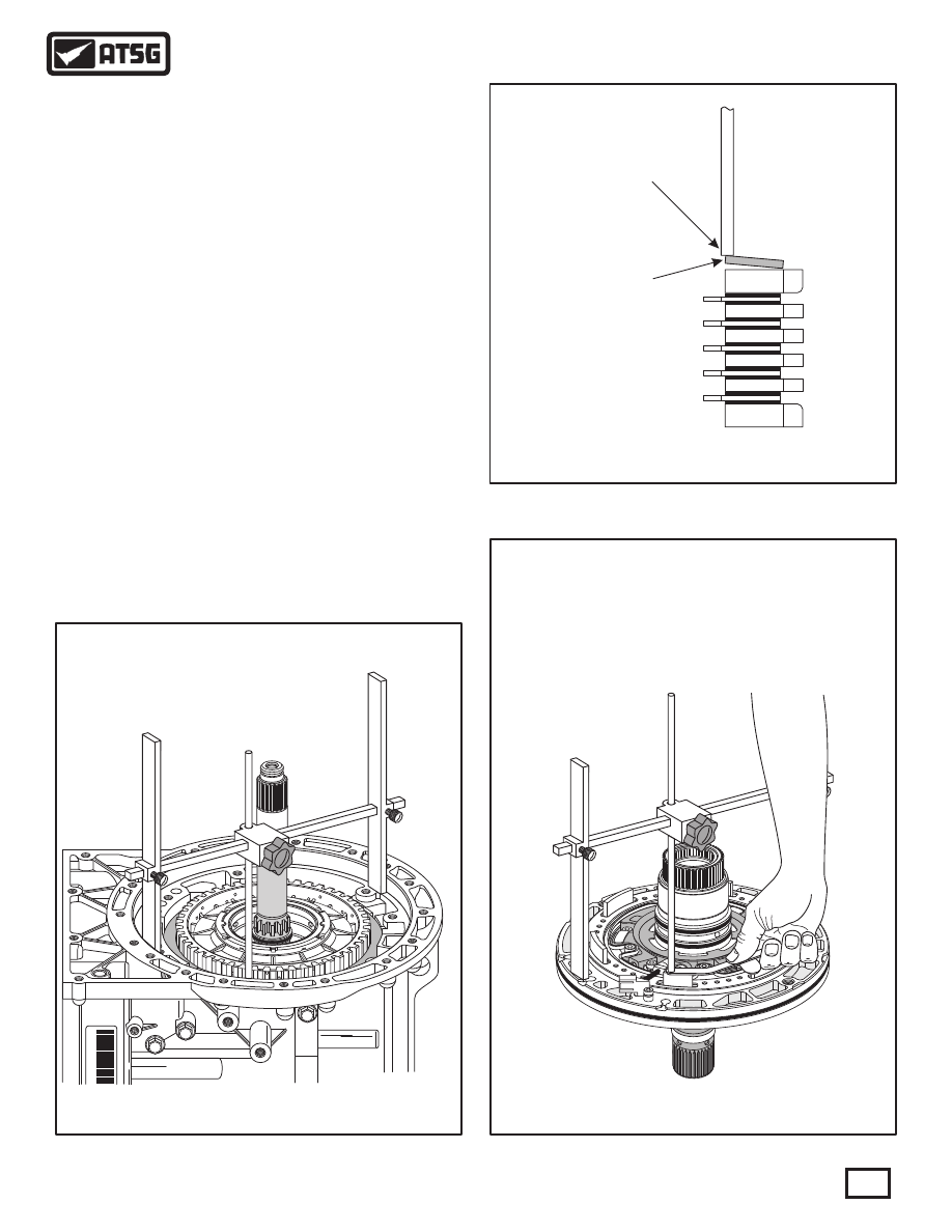
 41. Install "H" gage on the transmission case pump 
             surface, as shown in Figure 220, and lower the
             adjustment rod to the "high" point on the surface
             of the cushion plate and tighten adjustment rod 
       locking knob.
       Note: Tip of adjustment rod must be resting on
             the "high" point of cushion plate, as shown in
       Figure 221.
 42. Now turn "H" gage over and set it on completed
             oil pump assembly, as shown in Figure 223, with 
             adjustment rod over one leg of B1 clutch piston.
 43. Measure with feeler gauge between adjustment 
             rod and B1 clutch piston to determine the B1 
             clutch clearance, as shown in Figure 223.
       Note: There are no factory clutch clearance 
       specifications available, but the clearances 
             were the "traditional" .010" per friction plate
       through-out this unit.
 44. B1 clutch clearance should be approximately 
             .010" per friction plate installed, as shown in
       Figure 223.

B1 CUSHION

PLATE

B1 CUSHION

PLATE

TIP OF ADJUSTMENT

ROD MUST BE RESTING

ON HIGH POINT OF

CUSHION PLATE

TIP OF ADJUSTMENT

ROD MUST BE RESTING

ON HIGH POINT OF

CUSHION PLATE

* 2

0

SGL

 J0
0

0

3

7

Figure 220

Figure 222

Figure 221

B1 Clutch Clearance Should Be

Approximately .010" Per Friction

Plate Installed

WWW.ALL-TRANS.BY

TRANSMISSION ASSEMBLY (CONT'D)

Continued on Page 125

 45. Install "H" gage on the transmission case pump 
             surface, as shown in Figure 223, and lower the 
             adjustment rod to the surface of the number 1
             thrust washer and tighten the adjustment rod
       locking knob.
       Note: There is no pump to case gasket used on 
             the "09D" transmission to include in this
       measurement.
 46. Now turn "H" gage over and set it on completed 
             oil pump assembly, as shown in Figure 224, with 
             adjustment rod over the number 1 thrust washer
       hardened race.
 47. Measure with feeler gauge between adjustment 
             rod and hardened race to determine transmission
       end-play.
       Note: There are no selective washers available
       and no factory end-play specifications available.
 48. Transmission end-play for this unit should be
             0.304 MM (.012") to 0.609 MM (.024").
 49. Ensure number 1 thrust washer is still in place 
             on the K3 clutch housing   (See Figure 225).

Figure 224

Figure 225

Figure 223

3 U

* 20SGL

 J00037

* 20SGL

 J00037

Transmission End-Play Should Be

0.304 MM (.012") to 0.609 MM (.024")

 71  NUMBER 1 THRUST WASHER HARDENED RACE.

71

NUMBER 1 THRUST WASHER

STILL IN PLACE ON K3 CLUTCH

HOUSING

NUMBER 1 THRUST WASHER

STILL IN PLACE ON K3 CLUTCH

HOUSING

124

Copyright © 2010 ATSG

Copyright © 2010 ATSG

Copyright © 2010 ATSG

AUTOMATIC TRANSMISSION SERVICE GROUP

Technical Service Information

WWW.ALL-TRANS.BY

* 20SGL

 J00037

142

7

AT

 34  OIL PUMP RETAINING BOLTS, 34.5 MM (1.358") LONG (10 REQ).

34

* 20SGL

 J00037

14

2

7

AT

* 20SGL

 J00037

142

7

AT

TRANSMISSION ASSEMBLY (CONT'D)

Continued on Page 126

 50. Install completed oil pump assembly, as shown 
       in Figure 226.
       Note: You may have to rotate the turbine shaft
             which will rotate the front sun gear which must
             engage on splines of pump cover, for the pump
       to be fully seated.
 51. Once the pump is fully seated, install the ten oil 
             pump retaining bolts, as shown in Figure 227.
 52. Torque all ten of the oil pump retaining bolts to
             27 N·m (20 ft.lb.) using a criss-cross pattern, as 
       shown in Figure 228.

Figure 226

Figure 228

Figure 227

TORQUE ALL OIL PUMP BOLTS TO

27 N·M (20 FT.LB.)

125

Copyright © 2010 ATSG

Copyright © 2010 ATSG

Copyright © 2010 ATSG

AUTOMATIC TRANSMISSION SERVICE GROUP

Technical Service Information

WWW.ALL-TRANS.BY

A-

3

2

2

2

2

AISIN

AISIN

AISIN

AISIN

8 8

6 0

8 8

6 0

8 8

6 0

8 8

6 0

1

1

1

1

9A

N3

K01

755

9AN

3K017

62

8BA3

K0163

1

9A

N3

K01

748

9AN

3K

01

742

4AM3K03

O18

142

7

AT

MANUAL VALVE

ENGAGED

MANUAL VALVE

ENGAGED

Copyright © 2010 ATSG

50 50

63 63

142

7

A

T

A-3

2

2

2

2

AISIN

AISIN

AISIN

AISIN

8 8

6 0

8 8

6 0

8 8

6 0

8 8

6 0

1

1

1

1

9A

N3

K01755

9A

N3

K0

1762

8B

A3

K016

31

9A

N3

K01748

9AN3

K01742

4AM3K

03O18

29

29

COMPLETED VALVE

BODY ASSEMBLY

COMPLETED VALVE

BODY ASSEMBLY

30

 29  VALVE BODY TO CASE BOLT, 28.0 MM (1.102") LONG  (11 REQ).
 30  VALVE BODY TO CASE BOLT, 39.8 MM (1.566") LONG  (3 REQ).

B

B

B

B

B

B

B

B

B

B

B

A

A

A

 A = 39.8 MM   (1.566") IN LENGTH.
 B = 28.0 MM   (1.102) IN LENGTH.

VALVE BODY TO CASE BOLT LOCATIONS

Figure 229

Figure 231

Figure 230

TRANSMISSION ASSEMBLY (CONT'D)

Continued on Page 127

 53. Now set transmission on work bench with the 
             pan surface facing up, as shown in Figure 229.
 54. Install the completed valve body assembly, as
       shown in Figure 229. 
       Note: Ensure manual valve is engaged with the
       inside detent lever  (See Figure 230).
 55. Install the 14 valve body to case bolts in their 
             proper locations using Figure 231 as a guide.
 56. Torque all fourteen valve body to case bolts to
       11 N·m (97 in.lb.).

126

Copyright © 2010 ATSG

Copyright © 2010 ATSG

AUTOMATIC TRANSMISSION SERVICE GROUP

Technical Service Information

WWW.ALL-TRANS.BY


Content   ..  64  65  66  67   ..