Volkswagen Fox (2004 year). Manual - part 8
Note
♦
Before removing crankshaft, make sure that a proper surface
has been prepared to ensure that the speed sensor rotor is not
damaged, or does not touch another item.
♦
All bearing and running surfaces must be lubricated before
assembly.
WARNING
Always replace self-locking nuts and screws subject to angular
torque
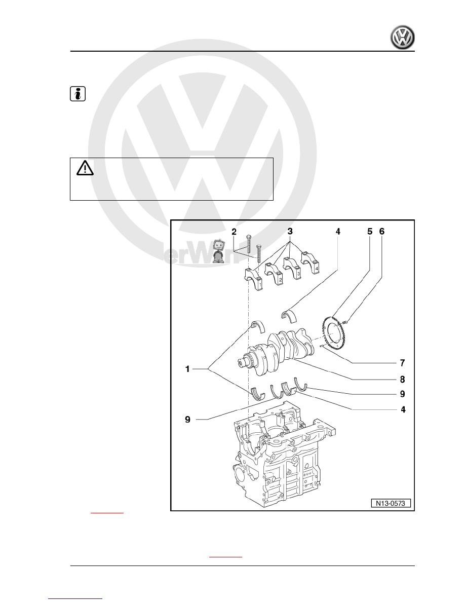
1 - Bearing shells 1, 2 and 4
❑ For bearing shells with‐
out oil groove.
❑ For engine block with oil
groove.
❑ Do not interchange
used bearing shells
(mark)
2 - 65 Nm + 90°
❑ Replace after each re‐
moval.
❑ To measure radial clear‐
ance, tighten to 65 Nm,
and no further.
3 - Bearing cap
❑ Bearing cap 1: Pulley
side.
❑ Bearing shell retaining
tabs (block/bearing cap)
4 - Bearing shell 3
❑ For bearing cap without
oil groove.
❑ For engine block with oil
groove.
5 - Speed sensor rotor
❑ To Engine speed sensor
- G28-
❑ Replace if damaged.
❑ Replace sensor rotor
each time bolts are loos‐
ened
❑ Remove and install.
⇒ page 30
6 - 10 Nm + 90°
❑ Replace after each removal.
7 - Fitted pin
❑ Check the projection from crankshaft
⇒ page 30
Fox 2004 ➤
4. Crankshaft - remove and install
29