Volkswagen Fox (2004 year). Manual - part 6
 

  Index      Volkswagen     Volkswagen Fox - service repair manual 2004 year


Search            copyright infringement  


Content   ..  4  5  6  7   ..


Volkswagen Fox (2004 year). Manual - part 6


– Drain engine oil.
– Remove crankcase 

⇒ page 68

 .

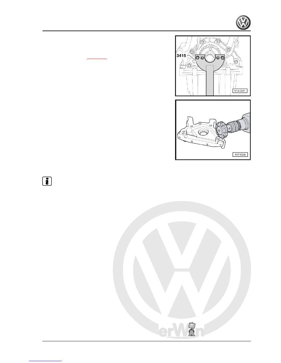
– Loosen front seal flange.
– Remove sealing flange, and release by tapping slightly with a

rubber headed hammer, if necessary.

– Remove seal residues on engine block with a flat spatula.
– Cover oil seal with a clean cloth.

– Remove the sealant residues from the sealing flange with a

rotary plastic brush (use eye protection).

– Clean the sealing surfaces. They must be free of oil and

grease.

2.2.2

Installation

Note

Observe the sealant expiration date.

The sealing flange must be installed within 5 minutes after ap‐

plying the sealant.

Fox 2004 ➤

2. Crankshaft flanges and flywheel - remove and install    

21


– Apply silicone sealant, as shown, on the clean sealing surface

of the sealing flange. The sealing compound bead must:

♦ Have a thickness of -arrows-: 2...3 mm.

Note

The sealant bead cannot be thicker, otherwise, the excess

sealant could pass to the crankshaft and block the strainer of

the oil suction tube, as well as run along the sealing surface

of the oil seal in the crankshaft.

Before applying the sealant, cover the oil seal with a clean

cloth.

– Fasten the sealing flange immediately and lightly tighten all

screws.

Note

Use the Guide sleeve -T10053/1- to fit the sealing flange with the

oil seal already installed.

– Tighten fastening screws of sealing flange by using an alter‐

nating tightening sequence. Tightening torque: 15 Nm.

– Remove excess sealant.
– Install crankcase 

⇒ page 68

 .

Note

After installation, the sealant should dry for approx. 30 minutes

before replenishing the engine with oil.

Install timing belt and adjust distribution times 

⇒ page 41

 .

– Install Poly-V belt 

⇒ page 14

 .

Fox 2004 ➤

22


frame - remove and install

Note

All bearing and running surfaces must be lubricated before as‐

sembly.

WARNING

Always replace self-locking nuts and screws subject to angular

torque

1 - Chain

❑ Observe fastening posi‐

tion 

⇒ page 25

 .

2 - 100 Nm +90°

❑ Replace after each re‐

moval.

❑ The angular torque

could be undertaken in

several stages.

❑ To loose and tighten,

use Multi-point spanner

-T10061- .

3 - Counterbalance

❑ It can be installed in one

position only. The holes

are displaced.

4 - Gear

❑ For counterbalance

shaft.

❑ It can be installed in one

position only. The holes

are displaced.

5 - Fastening sleeve
6 - 20 Nm + 90°

❑ Replace after each re‐

moval.

7 - Gear

❑ For oil pump.
❑ It can be installed in one

position only. The holes

are displaced.

8 - Cover

❑ With sealing tape.
❑ Clean strainer if soiled.

9 - 5 Nm
10 - Sealing ring

❑ Replace.

Fox 2004 ➤

3. Counterbalance shaft and retaining frame - remove and install    

23


❑ With 11.5-bar pressure relief valve.
❑ Before installing, check that both centering fastening sleeves are installed.

13 - Counterbalance shaft

❑ Remove and install 

⇒ page 25

 .

14 - Mounting frame

❑ Before installing, check that the securing guides for centralizing in the engine block are in their positions,

and the sealing ring is inserted in the mounting frame.

❑ Remove and install 

⇒ page 25

 .

15 - Sealing ring

❑ Replace.
❑ Check that it is firmly seated on the mounting frame.

16 - Engine block
17 - Gear
18 - 20 Nm
19 - Chain tensioning element with tensioning plate.

❑ To remove, immobilise with Locking pin -T10060- .
❑ Remove and install 

⇒ page 25

 .

20 - 8 Nm + 90°

❑ Replace after each removal.

Fox 2004 ➤

24


Content   ..  4  5  6  7   ..