Toyota Corolla Cross (2024 year). Manual in english - page 15
 

  Index      Toyota     Toyota Corolla Cross (2024 year). Manual in english


Search            copyright infringement  


Content      ..     13      14      15     


Toyota Corolla Cross (2024 year). Manual in english - page 15


449

8-1. Specifications

8

Vehicle

 specificatio

ns

An all season tire has “M+S” on the sidewall. A tire not marked “M+S” is a 
summer tire.

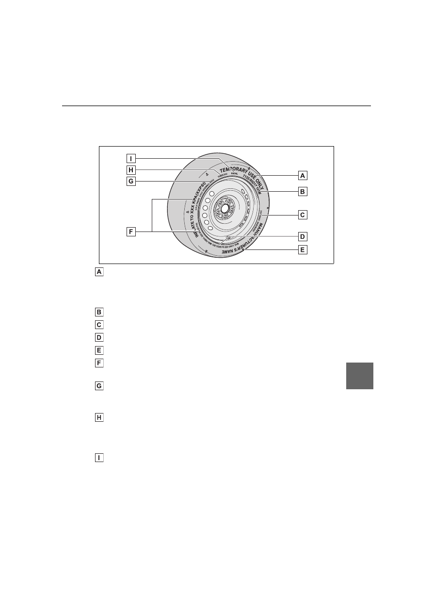
Compact spare tire

“TEMPORARY USE ONLY”

A compact spare tire is identified by the phrase “TEMPORARY USE ONLY” 
molded on its sidewall. This tire is designed for temporary emergency use 
only.

Tire size (

P.450)

DOT and Tire Identification Number (TIN) (

P.450)

Load limit at maximum cold tire inflation pressure (

P.360)

Location of treadwear indicators (

P.360)

Maximum cold tire inflation pressure (

P.443)

This means the pressure to which a tire may be inflated.

Tire ply composition and materials

Plies are layers of rubber-coated parallel cords. Cords are the strands 
which form the plies in a tire.

TUBELESS or TUBE TYPE

A tubeless tire does not have a tube and air is directly put into the tire. A 
tube type tire has a tube inside the tire and the tube maintains the air pres-
sure.

Radial tires or bias-ply tires

A radial tire has “RADIAL” on the sidewall. A tire not marked “RADIAL” is a 
bias-ply tire.

450

8-1. Specifications

Type A

DOT symbol

*

Tire Identification Number 
(TIN)

Tire manufacturer’s identifi-
cation mark

Tire size code

Manufacturer’s optional tire 
type code (3 or 4 letters)

Manufacturing week

Manufacturing year

*

: The DOT symbol certifies that the 

tire conforms to applicable Fed-
eral Motor Vehicle Safety Stan-
dards.

Type B

DOT symbol

*

Tire Identification Number 
(TIN)

Tire manufacturer’s identifi-
cation mark

Manufacturer’s code

Manufacturing week

Manufacturing year

*

: The  DOT  symbol  certifies that the 

tire conforms to applicable Fed-
eral Motor Vehicle Safety Stan-
dards.

Typical tire size information

The illustration indicates typical 
tire size.

Tire use (P = Passenger car, 
T = Temporary use)

Section width (millimeters)

Aspect ratio (tire height to 
section width)

Tire construction code (R = 
Radial, D = Diagonal)

Wheel diameter (inches)

Load index (2 digits or 3 dig-
its)

Typical DOT and Tire 
Identification Number 
(TIN)

Tire size

451

8-1. Specifications

8

Vehicle

 specificatio

ns

Speed symbol (alphabet with 
one letter)

Tire dimensions

Section width

Tire height

Wheel diameter

Bead

Sidewall

Shoulder

Tread

Belt

Inner liner

Reinforcing rubber

Carcass

Rim lines

Bead wires

Chafer

This information has been pre-
pared in accordance with regu-
lations issued by the National 
Highway Traffic Safety Adminis-
tration of the U.S. Department of 
Transportation.

It provides the purchasers 
and/or prospective purchasers 
of Toyota vehicles with informa-
tion on uniform tire quality grad-
ing.

Your Toyota dealer will help answer 
any questions you may have as you 
read this information.

DOT quality grades

All passenger vehicle tires must 
conform to Federal Safety 
Requirements in addition to 
these grades. Quality grades 
can be found where applicable 
on the tire sidewall between 
tread shoulder and maximum 
section width.

For example: Treadwear 200 Trac-
tion AA Temperature A

Treadwear

The treadwear grade is a com-
parative rating based on the 
wear rate of the tire when tested 
under controlled conditions on a 
specified government test 
course.

For example, a tire graded 150 

Tire section names

Uniform Tire Quality 
Grading

452

8-1. Specifications

would wear one and a half (1 - 1/2) 
times as well on the government 
course as a tire graded 100.
The relative performance of tires 
depends upon the actual conditions 
of their use. Performance may differ 
significantly from the norm due to 
variations in driving habits, service 
practices and differences in road 
characteristics and climate.

Traction AA, A, B, C

The traction grades, from high-
est to lowest, are AA, A, B and 
C, and they represent the tire’s 
ability to stop on wet pavement 
as measured under controlled 
conditions on specified govern-
ment test surfaces of asphalt 
and concrete.

A tire marked C may have poor 
traction performance.

Warning: The traction grade 
assigned to this tire is based on 
braking (straight ahead) traction 
tests and does not include corner-
ing (turning) traction.

Temperature A, B, C

The temperature grades are A 

(the highest), B, and C, repre-
senting the tire’s resistance to 
the generation of heat and its 
ability to dissipate heat when 
tested under controlled condi-
tions on a specified indoor labo-
ratory test wheel.

Sustained high temperature can 
cause the material of the tire to 
degenerate and reduce tire life, and 
excessive temperature can lead to 
sudden tire failure.

Grade C corresponds to a level of 
performance which all passenger 
car tires must meet under the Fed-
eral Motor Vehicle Safety Standard 
No. 109.

Grades B and A represent higher 
levels of performance on the labo-
ratory test wheel than the minimum 
required by law.

Warning: The temperature grades 
of a tire assume that it is properly 
inflated and not overloaded.

Excessive speed, underinflation, or 
excessive loading, either sepa-
rately or in combination, can cause 
heat buildup and possible tire fail-
ure.

Glossary of tire terminology

Tire related term

Meaning

Cold tire inflation pressure

Tire pressure when the vehicle has been 
parked for three hours or more, or has not 
been driven more than 1 mile or 1.5 km 
under that condition

Maximum inflation pressure

The maximum cold inflated pressure to 
which a tire may be inflated, shown on the 
sidewall of the tire

453

8-1. Specifications

8

Vehicle

 specificatio

ns

Recommended inflation pres-
sure

Cold tire inflation pressure recommended 
by a manufacturer

Accessory weight

The combined weight (in excess of those 
standard items which may be replaced) of 
automatic transmission, power steering, 
power brakes, power windows, power 
seats, radio and heater, to the extent that 
these items are available as fac-
tory-installed equipment (whether installed 
or not)

Curb weight

The weight of a motor vehicle with stan-
dard equipment, including the maximum 
capacity of fuel, oil and coolant, and if so 
equipped, air conditioning and additional 
weight optional engine

Maximum loaded vehicle 
weight

The sum of:

(a) Curb weight

(b) Accessory weight

(c) Vehicle capacity weight

(d) Production options weight

Normal occupant weight

150 lb. (68 kg) times the number of occu-
pants specified in the second column of 

Table 1

*

 that follows

Occupant distribution

Distribution of occupants in a vehicle as 

specified in the third column of Table 1

*


below

Production options weight

The combined weight of installed regular 
production options weighing over 5 lb. (2.3 
kg) in excess of the standard items which 
they replace, not previously considered in 
curb weight or accessory weight, including 
heavy duty brakes, ride levelers, roof rack, 
heavy duty battery, and special trim

Rim

A metal support for a tire or a tire and tube 
assembly upon which the tire beads are 
seated

Tire related term

Meaning

454

8-1. Specifications

Rim diameter (Wheel diame-
ter)

Nominal diameter of the bead seat

Rim size designation

Rim diameter and width

Rim type designation

The industry manufacturer’s designation 
for a rim by style or code

Rim width

Nominal distance between rim flanges

Vehicle capacity weight (Total 
load capacity)

The rated cargo and luggage load plus 150 
lb. (68 kg) times the vehicle’s designated 
seating capacity

Vehicle maximum load on the 
tire

The load on an individual tire that is deter-
mined by distributing to each axle its share 
of the maximum loaded vehicle weight, 
and dividing by two

Vehicle normal load on the tire

The load on an individual tire that is deter-
mined by distributing to each axle its share 
of curb weight, accessory weight, and nor-
mal occupant weight (distributed in accor-

dance with Table 1

*

 below), and dividing by 

two

Weather side

The surface area of the rim not covered by 
the inflated tire

Bead

The part of the tire that is made of steel 
wires, wrapped or reinforced by ply cords 
and that is shaped to fit the rim

Bead separation

A breakdown of the bond between compo-
nents in the bead

Bias ply tire

A pneumatic tire in which the ply cords that 
extend to the beads are laid at alternate 
angles substantially less than 90 degrees 
to the centerline of the tread

Carcass

The tire structure, except tread and side-
wall rubber which, when inflated, bears the 
load

Chunking

The breaking away of pieces of the tread 
or sidewall

Cord

The strands forming the plies in the tire

Tire related term

Meaning

455

8-1. Specifications

8

Vehicle

 specificatio

ns

Cord separation

The parting of cords from adjacent rubber 
compounds

Cracking

Any parting within the tread, sidewall, or 
innerliner of the tire extending to cord 
material

CT

A pneumatic tire with an inverted flange 
tire and rim system in which the rim is 
designed with rim flanges pointed radially 
inward and the tire is designed to fit on the 
underside of the rim in a manner that 
encloses the rim flanges inside the air cav-
ity of the tire

Extra load tire

A tire designed to operate at higher loads 
and at higher inflation pressures than the 
corresponding standard tire

Groove

The space between two adjacent tread ribs

Innerliner

The layer(s) forming the inside surface of a 
tubeless tire that contains the inflating 
medium within the tire

Innerliner separation

The parting of the innerliner from cord 
material in the carcass

Intended outboard sidewall

(a) The sidewall that contains a whitewall, 
bears white lettering, or bears manufac-
turer, brand, and/or model name molding 
that is higher or deeper than the same 
molding on the other sidewall of the tire, or

(b) The outward facing sidewall of an 
asymmetrical tire that has a particular side 
that must always face outward when 
mounted on a vehicle

Light truck (LT) tire

A tire designated by its manufacturer as 
primarily intended for use on lightweight 
trucks or multipurpose passenger vehicles

Load rating

The maximum load that a tire is rated to 
carry for a given inflation pressure

Maximum load rating

The load rating for a tire at the maximum 
permissible inflation pressure for that tire

Tire related term

Meaning

456

8-1. Specifications

Maximum permissible inflation 
pressure

The maximum cold inflation pressure to 
which a tire may be inflated

Measuring rim

The rim on which a tire is fitted for physical 
dimension requirements

Open splice

Any parting at any junction of tread, side-
wall, or innerliner that extends to cord 
material

Outer diameter

The overall diameter of an inflated new tire

Overall width

The linear distance between the exteriors 
of the sidewalls of an inflated tire, including 
elevations due to labeling, decorations, or 
protective bands or ribs

Passenger car tire

A tire intended for use on passenger cars, 
multipurpose passenger vehicles, and 
trucks, that have a gross vehicle weight 
rating (GVWR) of 10,000 lb. or less.

Ply

A layer of rubber-coated parallel cords

Ply separation

A parting of rubber compound between 
adjacent plies

Pneumatic tire

A mechanical device made of rubber, 
chemicals, fabric and steel or other materi-
als, that, when mounted on an automotive 
wheel, provides the traction and contains 
the gas or fluid that sustains the load

Radial ply tire

A pneumatic tire in which the ply cords that 
extend to the beads are laid at substan-
tially 90 degrees to the centerline of the 
tread

Reinforced tire

A tire designed to operate at higher loads 
and at higher inflation pressures than the 
corresponding standard tire

Section width

The linear distance between the exteriors 
of the sidewalls of an inflated tire, exclud-
ing elevations due to labeling, decoration, 
or protective bands

Sidewall

That portion of a tire between the tread 
and bead

Tire related term

Meaning

457

8-1. Specifications

8

Vehicle

 specificatio

ns

*

: Table 1 -Occupant loading and distribution for vehicle normal load for var-

ious designated seating capacities

Sidewall separation

The parting of the rubber compound from 
the cord material in the sidewall

Snow tire

A tire that attains a traction index equal to 
or greater than 110, compared to the 
ASTM E-1136 Standard Reference Test 
Tire, when using the snow traction test as 
described in ASTM F-1805-00, Standard 
Test Method for Single Wheel Driving Trac-
tion in a Straight Line on Snow-and 
Ice-Covered Surfaces, and which is 

marked with an Alpine Symbol (

) on at 

least one sidewall

Test rim

The rim on which a tire is fitted for testing, 
and may be any rim listed as appropriate 
for use with that tire

Tread

That portion of a tire that comes into con-
tact with the road

Tread rib

A tread section running circumferentially 
around a tire

Tread separation

Pulling away of the tread from the tire car-
cass

Treadwear indicators (TWI)

The projections within the principal 
grooves designed to give a visual indica-
tion of the degrees of wear of the tread

Wheel-holding fixture

The fixture used to hold the wheel and tire 
assembly securely during testing

Tire related term

Meaning

Designated seating 

capacity, Number of 

occupants

Vehicle normal load, 

Number of occupants

Occupant distribution in 

a normally loaded vehi-

cle

2 through 4

2

2 in front

5 through 10

3

2 in front, 1 in second 

seat

458

8-1. Specifications

11 through 15

5

2 in front, 1 in second 

seat, 1 in third seat, 1 in 

fourth seat

16 through 20

7

2 in front, 2 in second 

seat, 2 in third seat, 1 in 

fourth seat

Designated seating 

capacity, Number of 

occupants

Vehicle normal load, 

Number of occupants

Occupant distribution in 

a normally loaded vehi-

cle

459

8-2. Customization

8

Vehicle

 specificatio

ns

8-2.Customization

Changing by using the 

audio system screen

1

Select 

 on the main menu.

2

Select “Vehicle customise”.

3

Select the item to change the 

settings of from the list.

For functions that can be turned 
on/off, select 

 (ON)/ 


(OFF).

Changing by using the 

meter control switches

1

Select 

 or   of the 

multi-information display.

2

4.2-inch display meter: Press 

 or 

 to select the 

desired item to be custom-

ized.

3

7-inch display meter: Press 

 or 

 to select the 

desired item to be custom-

ized.

4

Press or press and hold 

.

The available settings will differ 
depending on if 

 is pressed or 

pressed and held. Follow the 

instructions on the display.

Some function settings are changed simultaneously with other func-

Customizable features

Your vehicle includes a vari-

ety of electronic features 

that can be personalized to 

suit your preferences. The 

settings of these features 

can be changed using the 

multi-information display, 

the audio system screen, or 

at your Toyota dealer.
Some of the customizable 

features are changed in 

conjunction with the set-

tings of My Settings. 

(

P.140)

Customizing vehicle fea-

tures

WARNING

During customization

As the engine needs to be run-

ning during customization, ensure 

that the vehicle is parked in a 

place with adequate ventilation. In 

a closed area such as a garage, 

exhaust gases including harmful 

carbon monoxide (CO) may col-

lect and enter the vehicle. This 

may lead to death or a serious 

health hazard.

NOTICE

During customization

To prevent battery discharge, 

ensure that the engine is running 

while customizing features.

Customizable features

460

8-2. Customization

tions being customized. Contact your Toyota dealer for further 
details.

Settings that can be changed using the audio system screen

Settings that can be changed using the meter control switches

Settings that can be changed by your Toyota dealer

Definition of symbols: O = Available, — = Not available

Gauges, meters and multi-information display (

P.74, 78, 81, 

84, 90)

Function

*1

Default setting Customized setting

Language

*4

English

French

O

O

Spanish

Units

*2

miles (MPG)

km (km/L)

O

O

km (L/100 km)

miles (MPG Impe-

rial)

Meter Style

*3, 4

Smart

Casual

O

Sporty

Dial Type

*3, 4

Tachometer

Speedometer

O

Simple (non-dial)

Eco Driving Indicator 

Light

*4

On

Off

O

Fuel economy display

Total average 

(Average fuel 

consumption 

[after reset])

Trip average (Aver-

age fuel consump-

tion [after start])

O

Tank average 

(Average fuel con-

sumption [after 

refuel])

Audio system linked dis-

play

*4

On

Off

O

AWD Control (AWD 

models)

*4

On

Off

O

Drive information type

*4

After start

After reset

O

461

8-2. Customization

8

Vehicle

 specificatio

ns

*1

: For details about each function: 

P.88

*2

: The default setting varies according to country.

*3

: 7-inch display

*4

: This setting changes in accordance with My Settings.

Door lock (

P.105, 110, 426)

*

: This setting changes in accordance with My Settings.

Drive information items 

(First item)

*4

Distance

Average vehicle 

speed

O

Elapsed time

Drive information items 

(Second item)

*4

Elapsed time

Average vehicle 

speed

O

Distance

Pop-up display

*4

On

Off

O

Suggestion function

*4

On

On (when the vehi-

cle is stopped)

O

O

Off

Function

Default setting Customized setting

Unlocking using a 
mechanical key

Driver’s door 

unlocked in 

one step, all 

doors 

unlocked in 

two step

All doors unlocked 

in one step

O

Speed linked door lock-

ing function

*

Off

On

O

O

Shift position linked door 

locking function

*

On

Off

O

O

Shift position linked door 

unlocking function

*

On

Off

O

O

Driver's door linked door 

unlocking function

*

Off

On

O

O

Function

*1

Default setting Customized setting

462

8-2. Customization

Smart key system

*1

 and wireless remote control (

P.105, 

120)

*1

: If equipped

*2

: This setting changes in accordance with My Settings.

Smart key system

*

 (

P.105, 120)

*

: If equipped

Function

Default setting Customized setting

Operating signal (Buzz-
ers)

5

Off

O

O

1 to 7

Operation signal (Emer-

gency flashers)

*2

On

Off

O

O

Time elapsed before 
automatic door lock 
function is activated if 
door is not opened after 

being unlocked

*2

60 seconds

30 seconds

O

O

120 seconds

Open door warning 
buzzer

On

Off

O

Function

Default setting Customized setting

Smart key system

On

Off

O

Smart door unlocking

Driver’s door

All the doors

O

O

Time elapsed before 
unlocking all the door 
when gripping and hold-
ing the driver’s door 
handle

2.0 seconds

Off

O

1.5 seconds

2.5 seconds

Number of consecutive 
door lock operations

2 times

As many as 

desired

O

463

8-2. Customization

8

Vehicle

 specificatio

ns

Wireless remote control (

P.102, 105, 110)

Power back door

*

 (

P.110)

*

: If equipped

Engine switch (

P.165)

Function

Default setting Customized setting

Wireless remote control

On

Off

O

Unlocking operation

Driver’s door 

unlocked in 

one step, all 

doors 

unlocked in 

two step

All doors unlocked 

in one step

O

O

Theft deterrent panic 
mode

On

Off

O

Locking operation when 
door opened

On

Off

O

O

Function

Default setting Customized setting

Power back door opera-
tions

On

Off

O

5 step configuration: 
Back door automatic 
open and stop position

5

1 to 5

O

Operation buzzer vol-
ume

3

1

O

2

Function

Customized setting

ACC customize

Enabling/Disabling ACC 
mode

On/Off

O

464

8-2. Customization

Power windows and moon roof

*

 (

P.134, 137)

*

: If equipped

Moon roof

*

 (

P.137)

*

: If equipped

Automatic light control system (

P.180)

*

: This setting changes in accordance with My Settings.

Lights (

P.180)

*

: Except for Canada

Function

Default setting Customized setting

Key linked operation

Off

On

O

Wireless remote control 
linked operation

Off

On (open only)

O

Wireless remote control 
linked operation signal 
(buzzer)

On

Off

O

Function

Default setting Customized setting

Linked operation of com-
ponents when key is 
used (open only)

Slide only

Tilt only

O

Linked operation of com-
ponents when wireless 
remote control is used

Slide only

Tilt only

O

Function

Default setting Customized setting

Light sensor sensitivity

*

Standard

-2 to 2

O

O

Windshield wiper linked 
headlight illumination

On

Off

O

Function

Default setting Customized setting

Daytime running light 
system

On

Off

*

O

O

Welcome lighting

On

Off

O

465

8-2. Customization

8

Vehicle

 specificatio

ns

PCS (Pre-Collision System) (

P.200)

*1

: The system is automatically enabled each time the engine switch is 

turned to ON.

*2

: This setting changes in accordance with My Settings.

LDA (Lane Departure Alert system) (

P.215)

*

: This setting changes in accordance with My Settings.

Dynamic radar cruise control (

P.229)

*

: This setting changes in accordance with My Settings.

Proactive Driving Assist (

P.221)

Function

Customized setting

PCS (Pre-Collision Sys-

tem)

*1

On, Off

O

Warning timing

*2

Later, Default, Earlier

O

Function

Customized setting

LDA (Lane Departure 

Alert) system

*

On, Off

O

Alert timing

*

Default, Earlier

O

Alert options

*

Vibration, Audible

O

Function

Customized setting

Acceleration setting

*

High, Mid, Low

O

Guide message

*

On, Off

O

Curve speed reduction

*

High, Mid, Low, Off

O

Function

Customized setting

Proactive Driving Assist 

(PDA)

*

On, Off

O

Support sensitivity

*

Low, Mid, High

O

466

8-2. Customization

*

: This setting changes in accordance with My Settings

RSA (Road Sign Assist)

*1

 (

P.227)

*1

: If equipped

*2

: This setting changes in accordance with My Settings.

Driver break suggestion (

P.215)

Stop & Start system (

P.246)

Deceleration Assist 

(DA)

*

On, Off

O

Obstacle Anticipation 

Assist (OAA)

*

On, Off

O

Function

Customized setting

RSA (Road Sign 

Assist)

*2

On, Off

O

Excess speed notifica-

tion method

*2

None, Visual, Visual and Audible

O

Other notifications 

method

*2

None, Visual, Visual and Audible

O

Excess speed notifica-

tion level

*2

5 mph (10 km/h), 3 mph (5 km/h), 1 

mph (2 km/h)

O

Function

Customized setting

Driver break suggestion

On, Off

O

Function

Default setting Customized setting

Change the Stop & Start 
system duration when 
the A/C is on

Standard

Extended

O

Function

Customized setting

467

8-2. Customization

8

Vehicle

 specificatio

ns

BSM (Blind Spot Monitor)

*

 (

P.252)

*

: If equipped

Intuitive parking assist

*

 (

P.268)

*

: If equipped

RCTA (Rear Cross Traffic Alert) function

*1

 (

P.258)

*1

: If equipped

*2

: The sound volume is linked among the Intuitive parking assist and RCTA

PKSB (Parking Support Brake)

*

 (

P.274)

*

: If equipped

Function

Default setting Customized setting

BSM (Blind Spot Moni-
tor)

On

Off

O

Outside rear view mirror 
indicator brightness

Bright

Dim

O

Alert timing for pres-
ence of approaching 
vehicle (sensitivity)

Intermediate

Early

O

Late

Function

Customized setting

Intuitive parking assist

On, Off

O

Buzzer volume

Level1, Level2, Level3

O

Function

Customized setting

RCTA (Rear crossing 
traffic alert) function

On, Off

O

Buzzer volume

*2

Level1, Level2, Level3

O

Function

Default setting Customized setting

PKSB (Parking Support 
Brake) function

On

Off

O

468

8-2. Customization

Safe Exit Assist (

P.263)

Automatic air conditioning system

*1

 (

P.300)

*1

: If equipped

*2

: This setting changes in accordance with My Settings.

Illumination (

P.310)

*

: If equipped

Function

Customized setting

Safe Exit Assist

On, Off

O

Outside rearview mir-
rors display

On, Off

O

Detection sensitivity

Low, Middle, High

O

Function

Default setting Customized setting

Switching between out-
side air and recirculated 
air mode linked to auto-
matic mode switch oper-

ation

*2

On

Off

O

O

A/C auto switch opera-

tion

*2

On

Off

O

O

Function

Default setting Customized setting

Time elapsed before the 
interior lights turn off

15 seconds

Off

O

O

7.5 seconds

30 seconds

Operation after the 
engine switch is turned 
off

On

Off

O

Operation when the 
doors are unlocked

On

Off

O

Operation when you 
approach the vehicle 
with the electronic key 

on your person

*

On

Off

O

469

8-2. Customization

8

Vehicle

 specificatio

ns

Vehicle customization

When the smart key system is off, 
Smart door unlocking cannot be 
customized.

When the doors remain closed 
after unlocking the doors and the 
automatic door lock function is 
activated, the signals will be gen-
erated in accordance with the 
operation signal (buzzer) and the 
operation signal (emergency 
flashers) settings.

In the following situations, cus-
tomize mode in which the set-
tings can be changed through 
the multi-information display 
will automatically be turned off

A warning message appears after 
the customize mode screen is dis-
played

The engine switch is turned off.

The vehicle begins to move while 
the customize mode screen is dis-
played.

470

8-3. Initialization

8-3.Initialization

*

: If equipped

Items to initialize

The following items must be initialized for normal system 
operation after such cases as the battery being reconnected, 
or maintenance being performed on the vehicle:

List of items to initialize

Item

When to initialize

Reference

Power back door

*

• After reconnecting or changing 

the battery

P.116

Message indicat-
ing maintenance is 
required

• After maintenance is performed

P.438

Tire pressure warn-
ing system

• When rotating the tires.
• When changing the tire.
• After registering the ID codes.
• When changing between two 

registered wheel sets.

P.365

471

9

9

For ow

ner

s

For owners

.

9-1. For owners

Reporting safety defects for 

U.S. owners...............

472

Reporting safety defects for 

Canadian owners ......

472

Seat belt instructions for 

Canadian owners (in 
French)......................

473

SRS airbag instructions for 

Canadian owners (in 
French)......................

474

Headlight aim instructions 

for Canadian owners (in 
French)......................

480

472

9-1. For owners

9-1.For owners

Reporting safety 

defects for U.S. own-

ers

If you believe that your vehicle 
has a defect which could 
cause a crash or could cause 
injury or death, you should 
immediately inform the 
National Highway Traffic 
Safety Administration 
(NHTSA) in addition to notify-
ing Toyota Motor Sales, 
U.S.A., Inc. (Toll-free: 
1-800-331-4331).

If NHTSA receives similar 
complaints, it may open an 
investigation, and if it finds 
that a safety defect exists in a 
group of vehicles, it may order 
a recall and remedy cam-
paign. However, NHTSA can-
not become involved in 
individual problems between 
you, your dealer, or Toyota 
Motor Sales, U.S.A., Inc.

To contact NHTSA, you may 
call the Vehicle Safety Hotline 
toll-free at 1-888-327-4236 
(TTY: 1-800-424-9153); go to 

http://www.safercar.gov

 ; or 

write to: Administrator, 
NHTSA, 1200 New Jersey 
Ave. SE., Washington, DC 
20590. You can also obtain 
other information about motor 
vehicle safety from 

http://www.safercar.gov

.

Reporting safety 

defects for Canadian 

owners

Canadian customers who 
wish to report a safety-related 
defect to Transport Canada, 
Defects Investigations and 
Recalls, may telephone the 
toll-free hotline 
1-800-333-0510, mail Trans-
port Canada-ASFAD, 330 
Sparks Street, Ottawa, ON, 
K1A 0N5, or complete the 
online form at 

https://www.tc.gc.ca/recalls

.

473

9-1. For owners

9

For ow

ner
s

Déroulez la sangle diagonale 

de telle sorte qu'elle passe 

bien sur l'épaule, sans pour 

autant être en contact avec le 

cou ou glisser de l'épaule.

Placez la sangle abdominale 

le plus bas possible sur les 

hanches.

Réglez la position du dossier 

de siège. Asseyez-vous le 

dos droit et calez-vous bien 

dans le siège.

Ne vrillez pas la ceinture de 

sécurité.

Traitement des ceintures de 

sécurité

Nettoyez avec un chiffon ou une 

éponge humidifiés avec de l'eau 

savonneuse tiède. Vérifiez 

régulièrement que les ceintures 

ne sont pas usées, effilochées 

ou entaillées excessivement.

Seat belt instructions 

for Canadian owners 

(in French)

The following is a French 

explanation of seat belt 

instructions extracted from 

the seat belt section in this 

manual.

See the seat belt section for 

more detailed seat belt 

instructions in English.

Utilisation correcte des 

ceintures de sécurité

Entretien et soin

AVERTISSEMENT

Détérioration et usure des 

ceintures de sécurité

Inspectez le système de ceintures 

de sécurité régulièrement. Con-

trôlez l'absence de coupures, 

d'effilochages et de pièces 

desserrées. N'utilisez pas une 

ceinture de sécurité endommagée 

avant qu'elle ne soit remplacée. 

Une ceinture de sécurité endom-

magée ne permet pas de protéger 

un occupant de blessures graves 

ou mortelles.

474

9-1. For owners

Emplacement des coussins gonflables SRS

Coussins gonflables frontaux SRS

Coussin gonflable conducteur/coussin gonflable du passager 
avant SRS

Participe à la protection de la tête et du thorax du conducteur et du pas-
sager avant contre les chocs contre les éléments de l'habitacle

Coussin gonflable de genoux SRS

Participe à la protection du conducteur

Coussins gonflables latéraux SRS

• Contribuent à réduire l’impact au niveau du thorax des occupants des 

sièges avant

SRS airbag instructions for Canadian owners (in 

French)

The following is a French explanation of SRS airbag instruc-
tions extracted from the SRS airbag section in this manual.

See the SRS airbag section for more detailed SRS airbag instruc-
tions in English.

Système de coussins gonflables SRS

475

9-1. For owners

9

For ow

ner
s

• Contribuent à réduire l’impact au niveau du thorax des occupants des 

sièges arrière latéraux

Coussins gonflables latéraux et rideaux SRS

Coussins gonflables rideaux SRS

• Contribuent à réduire l’impact au niveau de la tête des occupants des 

sièges avant et des sièges arrière latéraux

• Peut contribuer à empêcher les occupants d’être éjectés du véhicule en 

cas de tonneau

Votre véhicule est équipé de COUSSINS GONFLABLES INTELLI-

GENTS conçus selon les normes de sécurité américaines applica-

bles aux véhicules à moteur (FMVSS208). L'ensemble des capteurs 

de coussins gonflables (ECU) régule le déploiement des coussins 

gonflables sur la base des informations qu'il reçoit des capteurs, 

etc., indiqués ci-dessus dans le schéma illustrant les composants du 

système. Parmi ces informations figurent la gravité du choc et l'occu-

pation du véhicule par les passagers. Le déploiement rapide des 

coussins gonflables est obtenu au moyen d'une réaction chimique 

dans les dispositifs pyrotechniques, qui produit un gaz inoffensif per-

mettant d'amortir le mouvement des occupants.

AVERTISSEMENT

Précautions relatives aux 

coussins gonflables SRS

Respectez les précautions suiva-

ntes concernant les coussins gon-

flables SRS.

Le non-respect de ces précau-

tions peut occasionner des bless-

ures graves, voire mortelles.

Le conducteur et tous les pas-

sagers du véhicule doivent por-

ter correctement leur ceinture 

de sécurité.

Les coussins gonflables SRS 

sont des dispositifs supplémen-

taires à utiliser avec les cein-

tures de sécurité.

476

9-1. For owners

AVERTISSEMENT

Le coussin gonflable conduc-

teur SRS se déploie avec une 

force considérable, pouvant 

occasionner des blessures 

graves, voire mortelles, si le 

conducteur se trouve très près 

du coussin gonflable. L'autorité 

fédérale chargée de la sécurité 

routière aux États-Unis 

(NHTSA) conseille:

La zone à risque du coussin gon-

flable conducteur se situant dans 

les premiers 2 à 3 in. (50 à 75 

mm) de déploiement, vous placer 

à 10 in. (250 mm) de votre cous-

sin gonflable conducteur vous 

garantit une marge de sécurité. 

Cette distance est à mesurer 

entre le centre du volant et le ster-

num. Si vous êtes assis à moins 

de 10 in. (250 mm), vous pouvez 

changer votre position de con-

duite de plusieurs façons:
• Reculez votre siège le plus pos-

sible, de manière à pouvoir 

encore atteindre confortable-

ment les pédales.

• Inclinez légèrement le dossier 

du siège.

Bien que les véhicules aient une 

conception différente, un grand 

nombre de conducteurs peu-

vent s'asseoir à une distance de 

10 in. (250 mm), même avec le 

siège conducteur complètement 

avancé, simplement en inclinant 

un peu le dossier de siège. Si 

vous avez des difficultés à voir 

la route après avoir incliné le 

dossier de votre siège, utilisez 

un coussin ferme et antidéra-

pant pour vous rehausser ou 

remontez le siège si votre 

véhicule est équipé de cette 

fonction.

• Si votre volant est réglable, 

inclinez-le vers le bas. Cela a 

pour effet d'orienter le coussin 

gonflable en direction de votre 

poitrine plutôt que de votre tête 

et de votre cou.

Si vous attachez une rallonge 

de ceinture de sécurité aux bou-

cles de ceinture de sécurité 

avant, sans l'attacher au pêne 

de la ceinture de sécurité, les 

coussins gonflables frontaux 

SRS déterminent que le con-

ducteur et le passager avant ont 

attaché leur ceinture de sécu-

rité, bien que la ceinture de 

sécurité ne soit pas attachée. 

Dans ce cas, les coussins gon-

flables frontaux SRS peuvent 

ne pas se déployer correcte-

ment en cas de collision, pou-

vant occasionner des blessures 

graves, voire mortelles. Veillez 

à porter la ceinture de sécurité 

avec la rallonge de ceinture de 

sécurité.

Le coussin gonflable passager 

avant SRS se déploie égale-

ment avec une force con-

sidérable, pouvant occasionner 

des blessures graves, voire 

mortelles, si le passager avant 

se trouve très près du coussin 

gonflable. Le siège du passager 

avant doit être éloigné le plus 

possible du coussin gonflable 

en réglant le dossier de siège 

de façon à ce que le passager 

avant soit assis bien droit dans 

le siège.

477

9-1. For owners

9

For ow

ner
s

AVERTISSEMENT

Les nourrissons et les enfants 

qui ne sont pas correctement 

assis et/ou attachés peuvent 

être grièvement blessés ou tués 

par le déploiement d'un coussin 

gonflable. Un nourrisson ou un 

enfant trop petit pour utiliser une 

ceinture de sécurité doit être 

correctement attaché au moyen 

d'un siège de sécurité enfant. 

Toyota recommande vivement 

d'installer tous les nourrissons 

et enfants sur les sièges arrière 

du véhicule et de prévoir pour 

eux des systèmes de retenue 

adaptés. Les sièges arrière sont 

plus sûrs pour les nourrissons 

et les enfants que le siège du 

passager avant.

Ne vous asseyez pas sur le 

bord du siège et ne vous 

appuyez pas contre la planche 

de bord.

Ne laissez pas un enfant rester 

debout devant le coussin gon-

flable passager avant SRS ou 

s'asseoir sur les genoux du pas-

sager avant.

Ne laissez pas les occupants 

des sièges avant voyager avec 

un objet sur les genoux.

Ne vous appuyez pas contre la 

porte, le rail latéral de toit ou les 

montants avant, latéraux et 

arrière.

Ne laissez personne s'age-

nouiller sur les sièges passag-

ers en appui contre la porte ou 

sortir la tête ou les mains à 

l'extérieur du véhicule.

Ne fixez rien et ne posez rien 

sur des emplacements tels que 

la planche de bord, la garniture 

du volant et la partie inférieure 

du tableau de bord.

Ces éléments peuvent se trans-

former en projectiles lorsque les 

coussins gonflables conducteur, 

passager avant et genoux SRS 

se déploient.

478

9-1. For owners

AVERTISSEMENT

Véhicules sans système 

d'accès et de démarrage mains 

libres: Ne fixez pas d'objets 

lourds, pointus ou très durs aux 

clés.

Ne suspendez aucun cintre ou 

objet dur aux crochets à vête-

ments. Tous ces objets pour-

raient se transformer en 

projectiles et causer des bless-

ures graves, voire mortelles en 

cas de déploiement des couss-

ins gonflables rideaux SRS.

Si un cache en vinyle est placé 

sur la zone où le coussin gon-

flable de genoux du conducteur 

SRS se déploie, assurez-vous 

de le retirer.

N'utilisez aucun accessoire de 

siège recouvrant les zones de 

déploiement des coussins gon-

flables latéraux SRS et du cous-

sin gonflable de coussin de 

siège SRS, car il risque de 

gêner le déploiement des cous-

sins gonflables SRS. De tels 

accessoires peuvent empêcher 

les coussins gonflables latéraux 

et le coussin gonflable de cous-

sin de siège de s'activer cor-

rectement, désactiver le 

système ou entraîner le déploie-

ment accidentel des coussins 

gonflables latéraux et du cous-

sin gonflable de coussin de 

siège, occasionnant des bless-

ures graves, voire mortelles.

Évitez de faire subir des chocs 

ou des pressions excessives 

aux parties renfermant les com-

posants de coussins gonflables 

SRS ou aux portes avant.

En effet, cela pourrait entraîner 

un dysfonctionnement des 

coussins gonflables SRS.

Ne touchez aucun composant 

immédiatement après le 

déploiement (gonflage) des 

coussins gonflables SRS, car ils 

peuvent être chauds.

Si vous avez des difficultés à 

respirer après le déploiement 

des coussins gonflables SRS, 

ouvrez une porte ou une vitre 

pour faire entrer de l'air frais, ou 

bien descendez du véhicule si 

cela ne présente pas de danger. 

Essuyez tout résidu dès que 

possible afin d'éviter d'éventu-

elles irritations de la peau.

Si les parties renfermant les 

coussins gonflables SRS, 

comme les garnitures du volant 

et des montants avant et 

arrière, sont endommagées ou 

craquelées, faites-les remplacer 

par votre concessionnaire Toy-

ota.

Ne placez rien sur le siège du 

passager avant, comme un 

coussin par exemple. Cela a 

pour conséquence de répartir le 

poids du passager sur toute la 

surface du siège, ce qui 

empêche le capteur de détecter 

correctement le poids du pas-

sager. En conséquence, les 

coussins gonflables frontaux 

SRS du passager avant ris-

quent de ne pas se déployer en 

cas de collision.

479

9-1. For owners

9

For ow

ner
s

AVERTISSEMENT

Modification et mise au rebut 

des composants du système 

de coussins gonflables SRS

Ne mettez pas votre véhicule au 

rebut et ne procédez à aucune 

des modifications suivantes sans 

consulter votre concessionnaire 

Lexus. Les coussins gonflables 

SRS peuvent ne pas fonctionner 

correctement ou se déployer invo-

lontairement, ce qui peut provo-

quer des blessures graves, voire 

mortelles.

Dépose, repose, démontage ou 

réparation des coussins gonfla-

bles SRS

Réparation, dépose ou modifi-

cation des pièces suivantes ou 

de leurs alentours

• Volant
• Tableau de bord
• Planche de bord
• Sièges
• Garnissage des sièges
• Montants avant
• Montants latéraux
• Montants arrière
• Rails latéraux de toit
• Panneaux de portes avant
• Garniture de porte avant
• Haut-parleurs de porte avant

Modifications des panneaux de 

portes avant (par exemple, 

perçage de trous dans les pan-

neaux)

Réparation ou modification des 

pièces suivantes ou de leurs 

alentours

• Aile avant
• Pare-chocs avant
• Côtés de l'intérieur du véhicule

Installation des pièces suiva-

ntes ou accessoires

• Pare-buffle ou pare-kangourou
• Chasse-neige
• Treuils
• Porte-bagages de toit (sur 

modèles équipés)

Modifications de la suspension 

du véhicule

Installation d'appareils électro-

niques tels que les émet-

teurs/récepteurs radios mobiles 

et les lecteurs CD

Modifications apportées à votre 

véhicule pour les personnes 

atteintes d'un handicap phy-

sique

480

9-1. For owners

Boulon de réglage A

Boulon de réglage B

Vérifiez que le réservoir de 
carburant du véhicule est 
plein et que la zone autour 
des phares n'est pas 
déformée.

Stationnez le véhicule sur une 
surface plane.

Assurez-vous que la pression 
de gonflage des pneus est au 
niveau recommandé.

Faites asseoir quelqu'un dans 
le siège conducteur.

Balancez le véhicule plu-
sieurs fois.

1

À l'aide d'un tournevis cruci-
forme, tournez le boulon A 
dans n'importe quel sens.

Mémorisez le sens dans lequel 
vous avez tourné et le nombre de 
tours.

2

Tournez le boulon B du 
même nombre de tours dans 
le même sens qu'à l'étape 

1

.

Si vous n'arrivez pas à régler le 
phare en procédant de la sorte, 
confiez le véhicule à votre conces-
sionnaire Toyota pour qu'il règle le 
faisceau des phares.

Headlight aim instruc-

tions for Canadian 

owners (in French)

The following is a French 
explanation of headlight aim 
instructions from the head-
light aim section in this 
manual.

Boulons de réglage du 
mouvement vertical

Avant de vérifier le 
réglage des phares

Réglage du faisceau des 
phares


Content      ..     13      14      15