Toyota Prius Plug-in Hybrid (2023 year). Manual in english - page 8
 

  Index      Toyota     Toyota Prius Plug-in Hybrid (2023 year). Manual in english


Search            copyright infringement  


Content      ..     6      7      8      9     ..


Toyota Prius Plug-in Hybrid (2023 year). Manual in english - page 8


128

2-2. Charging

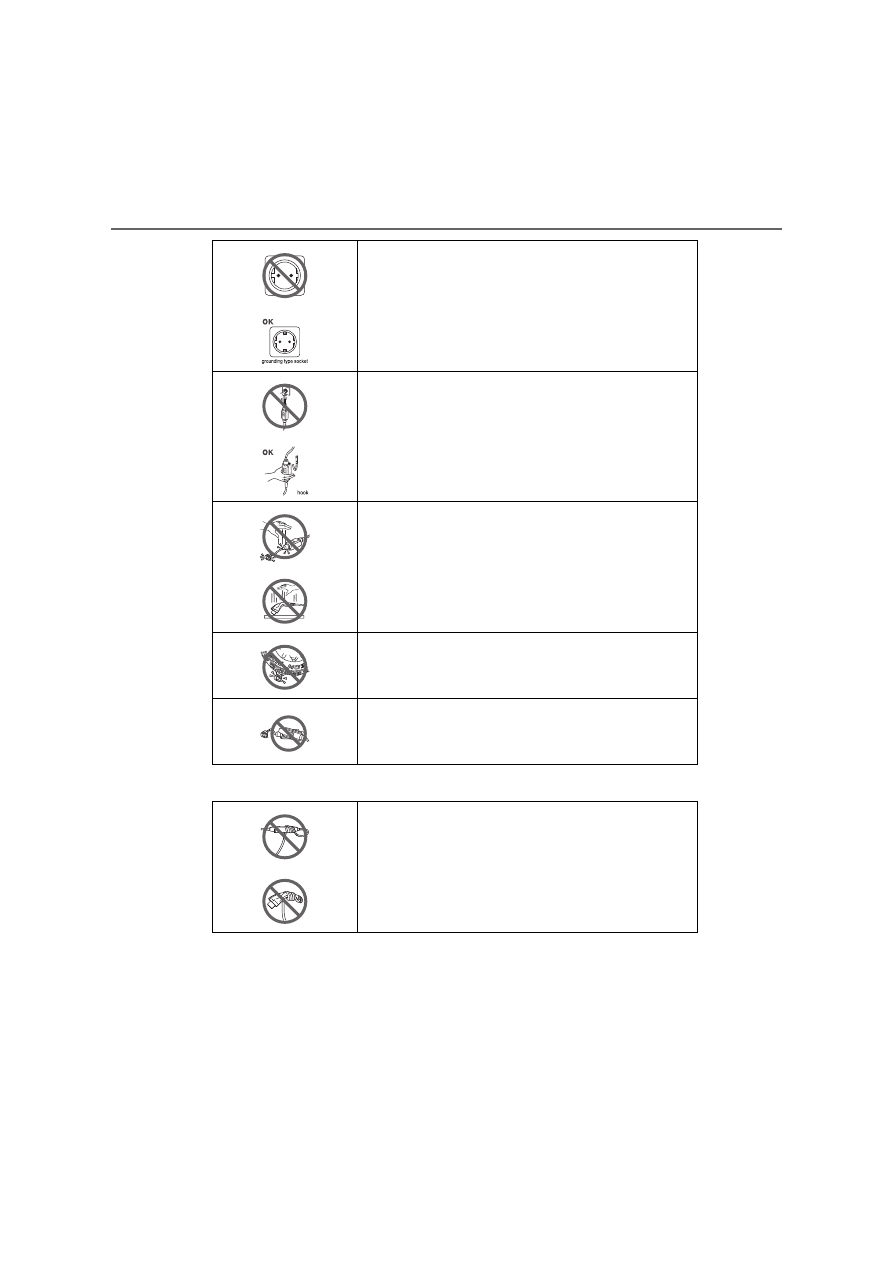
Caution symbols

To reduce the risk of electric shock, connect only to
a properly grounding type socket.

Do not hang the CCID (Charging Circuit Interrupting
Device) on the plug. Ensure the CCID (Charging
Circuit Interrupting Device) is supported.

Do not subject the charging cable, charging connec-
tor, plug or CCID (Charging Circuit Interrupting
Device) to strong force or impact.

Do not place heavy objects on the charging cable,
charging connector, plug or CCID (Charging Circuit
Interrupting Device).

Do not use this device if the charging cable is
frayed, has broken insulation, or any other signs of
damage.

Do not wind the power cord or charging cable
around the CCID (Charging Circuit Interrupting
Device) or charging connector.

129

2-2. Charging

2

P

lu

g

-in

 hy
br

id

 s

ys

tem

Information symbols

This device may not operate if used with IT or other
unearthed systems such as an isolated winding
generator or isolating transformer.

This device has a non-switched protective conduc-
tor.

Do not use this device at an altitude over 4000
meter.

130

2-2. Charging

Smart lid & connector locking system

Smart lid system
Operating the charging port lid carrying the electronic key on your
person, for example in your pocket, can unlock only the charging
port lid with the doors of the vehicle locked.
Charging connector locking system
When the charging connector is inserted straight as far as possible,
it will automatically lock.
Carry an electronic key and press the charging connector lock
switch to unlock the charging connector.

It can be used to prevent the charging cable removed or stolen while
charging.

Antenna location

P. 283

Effective range (areas within which the electronic key is detected)

P. 284

When carrying the electronic key on your person, for example in
your pocket, the charging port lid and the charging connector
can be locked or unlocked.

Smart lid & connector locking system operation

1

2

131

2-2. Charging

2

P

lu

g

-in

 hy
br

id

 s

ys

tem

Unlocking the charging port lid

Pressing the rear edge of the
charging port lid (the position
shown in the illustration) carry-
ing the electronic key on your
person, for example in your
pocket, can unlock the charging
port lid.

Push and take your hand away
to slightly open the charging port
lid.

Locking the charging port lid

Close the charging port lid
and press the rear edge of
the charging port lid (the
position shown in the illustra-
tion).

Using the smart lid system

1

132

2-2. Charging

Locking the doors using the smart entry & start system or wire-
less remote control. (

P. 273)

The charging port lid will be locked.
If the charging port lid is closed with the doors locked, the charging port
lid locks.

Charging port lid

If the rear edge of the charging port lid (the position shown in the illustra-
tions on P. 112 and 131) is pressed when the doors are locked and you are
not carrying the electronic key, the charging port lid opens slightly, but
remains locked. Carry an electronic key or unlock the doors, and then press
the charging port lid twice to open it.

If the charging port lid is opened and closed repeatedly, the charging port lid
lock may not operate in order to protect the system. In this case, press the
charging port lid twice after a while.

If the smart entry & start system has been deactivated in a customized
setting

The smart lid & connector locking system will also be deactivated. If the smart
entry & start system has been deactivated in a customized setting, the
charging port lid can be locked and unlocked by performing the following pro-
cedures.

Locking the charging port lid

Close the charging port lid. (

P. 112)

Locking the doors using the wireless remote control or door lock switch.
(

P. 273, 275)

The charging port lid can be locked if the steps   and   are performed in
reverse.

Unlocking the charging port lid

Unlocking the doors using the wireless remote control or door lock
switch. (

P. 273, 275)

Open the charging port lid. (

P. 112)

2

1

2

1

2

1

2

133

2-2. Charging

2

P

lu

g

-in

 hy
br

id

 s

ys

tem

If the charging port lid does not open

If the charging port lid does not open when using the normal procedure, it can
be opened in an emergency by performing the following steps.

Open the back door. (

P. 278)

Prepare the wheel nut wrench. (

P. 613)

Insert a wheel nut wrench as shown in the illustration.

Press the center of the rear edge of the charging port lid to open it. 
(

P. 112)

This unlocking method is a temporary correction procedure for emergency
use only. If the problem persists, have the vehicle inspected by any autho-
rized Toyota retailer or Toyota authorized repairer, or any reliable repairer
immediately.

Pull the knob and remove the cover
shown in the illustration.

Insert the end of the wheel nut
wrench along the cutout of the cover
installation area.
Temporarily place the L-shaped part
of the wheel nut wrench where it con-
tacts the deck board.
(Place the wheel nut wrench so that it
is perpendicular to the work hole.)

From the condition in step  , insert the
wheel nut wrench upwards into the
vehicle.
Pressing the emergency release lever
inside the work hole will unlock the
charging port lid.

1

2

3

4

1

2

5

4

6

134

2-2. Charging

Carry the electronic key on your person, for example in your pocket.

Locking the charging connector

Firmly insert the charging con-
nector into the charging inlet.
(

P. 157)

When the charging connector is
inserted straight as far as possi-
ble, it will automatically lock.
If the charging connector is not
firmly inserted, locking operation
will be performed several times.

Unlocking the charging connector

Press the charging connector
lock switch.

The charging connector will be
unlocked.

Using the charging connector locking system

135

2-2. Charging

2

P

lu

g

-in

 hy
br

id

 s

ys

tem

Charging connector locking system

If the charging connector lock switch is operated repeatedly, the connector
locking system may not work to protect the system. In this case, wait for a
while before operating the switch again.

The charging connector locking system does not guarantee to prevent theft
of the charging cable, and is not necessarily effective for all the situations.

When the charging connector cannot be inserted into the charging inlet

If the smart entry & start system has been deactivated in a customized
setting

The smart lid & connector locking system will also be deactivated. If the smart
entry & start system has been deactivated in a customized setting, the
charging connector can be unlocked by performing the following procedure.

Unlock the doors using the wireless remote control or door lock switch.
(

P. 273, 275)

Press the charging connector lock switch.
The charging connector will unlock.

Check that the connector lock pin is not
lowered.
If the connector lock pin is lowered, the
connector lock is operating. Carry an
electronic key or unlock the doors, and
then press the charging connector lock
switch to unlock the connector lock and
check that the connector lock pin is not
lowered.

Connector lock pin

1

2

136

2-2. Charging

If the charging cable cannot be unlocked

If the charging connector cannot be unlocked by pressing the charging con-
nector lock switch even after carrying an electronic key or unlocking the
doors, the charging connector can be unlocked by operating the emergency
release lever.

Approximately 50 mm (2.0 in.)
Approximately 20 mm (0.9 in.)
Open the back door. (

P. 278)

Pull the knob and remove the cover as
shown in the illustration.

Insert a hand from the lower side of the
vehicle obliquely upward, and hook a
finger to the emergency release lever.

Move the emergency release lever in
the direction shown in the illustration.

*

The charging connector is unlocked and
can be removed.

*

: Make sure to move in the direction

shown in the illustration. Applying force
in other directions may damage the
emergency release lever.

1

2

1

2

3

4

137

2-2. Charging

2

P

lu

g

-in

 hy
br

id

 s

ys

tem

Reinstall the cover to the its original position.

This method is a temporary correction procedure for emergency use only. If
the problem persists, have the vehicle inspected by any authorized Toyota
retailer or Toyota authorized repairer, or any reliable repairer immediately.
Do not operate the emergency release lever when the charging connector
can be unlocked in the normal procedure.

When recharging or replacing the 12-volt battery

P. 702

WARNING

When connecting the charging connector to the charging inlet

5

Be careful not to touch the charging port
lid lock portion.
When the connector lock operates, the
charging port lid lock will also operate.
The charging port lid lock pin may hit a
hand, resulting in an injury.

Charging port 
lid lock pin

138

2-2. Charging

NOTICE

When inserting the charging connector

Observe the following precautions. Failure to do so may cause a malfunc-
tion in the charging connector locking system.

Check that the charging connector is compatible with this vehicle
A charging connector of the different type or a charging connector with
damaged or deformed insertion part may not be locked.

Do not operate the charging connector lock switch before the charging
connector is connected

Do not apply excessive force to the charging connector after the charging
connector is inserted
When removing the charging connector, make sure to unlock the charging
connector.

139

2

2-2. Charging

P

lu

g

-in

 hy
br

id

 s

ys

tem

Power sources that can be used

Connect to an AC 220 V - 240 V socket with a Residual Current Cir-
cuit-Breaker (RCCB) and a circuit breaker. Use of a 13A individual
circuit is strongly recommended to ensure charging cable will oper-
ate properly. 

We strongly recommend that you use an exclusive connection from
the junction box for charging.
If you connect on a socket that is on a shared circuit, and other
electrical appliances are used on other sockets on the same circuit,
then the circuit breaker might trip.

*

Ensure that the junction box is equipped with a Residual Current
Circuit-Breaker (RCCB). If it is not, have one installed by a duly
qualified professional.

When charging outdoors, make sure to connect to a rain-tight
socket that is certified for outdoor use.
Checking Residual Current Circuit-Breaker (RCCB) operation
before its use is recommended.

Check whether there are any local EV-charging regulations in
place, and adhere to them.

*

: For detailed information, consult an electrician.

An external power source that fulfills the following criteria is
necessary for charging this vehicle. Confirm this before
charging.

WARNING

Warnings for electrical faults

Make sure to observe the precautions in this Owner’s Manual when
charging the vehicle.
Failure to use a power source that fulfills the requirements, or failure to
observe regulations while charging could lead to an accident, possibly
resulting in death or serious injury.

Power sources

140

2-2. Charging

The charging environment

For safe charging, the following charging equipment and settings are recom-
mended.

Rain-tight socket 
When charging outdoors, connect the plug to a rain-tight socket, and ensure
that the plug remains waterproof while the plug is connected.

Dedicated circuit
• To reduce the risk of fire, connect only to an at least 13A branch circuit

with an over-current protection.

• To reduce the risk of electric shock when working with the plug, connect

to a socket that has a Residual Current Circuit-Breaker (RCCB) installed.

Remote switch 
Allows the electricity from the socket to be interrupted by operating a switch,
thus allowing safe removal and insertion of the plug on rainy days.

When your circuit breaker trips during charging

The upper limit of the charging current can be changed in the “Vehicle Set-
tings” settings on the multi-information display.

Press 

 or 

 of the meter control switches to select 

 (“Vehicle

Settings”) in the 

 screen, and then press 

.

Press 

 or 

 of the meter control switches to select “Charge Settings”,

and then press 

.

The “Charge Settings” screen will display.

Press 

 or 

 of the meter control switches to select “Charge Current”,

and then press 

.

The “Charge Current” screen will display.

Press 

 or 

 of the meter control switches to select “8A”, and then

press .

The maximum charging current during charging will be restricted to 8A.

*

If the breaker still trips while charging, even after changing the upper limit of
the charging current, check if the connected power source meets the speci-
fied charging conditions. (

P. 139)

*

: Restricting the charging current will lengthen the charging time.

1

2

3

4

141

2-2. Charging

2

P

lu

g

-in

 hy
br

id

 s

ys

tem

WARNING

Power sources precautions

Observe the following precautions.
If you do not follow them, fire, electrical shock and/or damages may occur,
possibly resulting in death or serious injury.

Connect to an AC 220 V - 240 V socket with a Residual Current Circuit-
Breaker (RCCB) and supplied by a circuit breaker in line with local regula-
tions. Use of an individual circuit provided with at least 13A is strongly rec-
ommended.

Use of a block heater socket which fails to meet the requirements is pro-
hibited for charging.

Make sure to connect the charging connector and charging inlet directly.
Do not connect a converting adaptor or extension cord between the
charging connector and charging inlet.

Do not connect the charging cable to a
multi-socket adaptor, multi-plugs, or
conversion plug.

Connecting the charging cable to an
extension cord is strictly prohibited. The
extension cord may overheat and does
not contain a Residual Current Circuit-
Breaker (RCCB). 
The leakage detection function of the
CCID (Charging Circuit Interrupting
Device) may not operate correctly.

Do not connect to a power strip.

142

2-2. Charging

Charging methods

Charging from an external power source (

P. 155)

This is a charging method used when charging from an AC socket
(220 V-240 V) with the charging cable equipped to the vehicle or
charging at a public charging station.

The charging start time (or departure time) and day can be set to carry
out charging using the charging schedule at the desired date and time.
(

P. 166)

Using the hybrid battery (traction battery) charge mode 
(

P. 89)

The plug-in hybrid system can be switched to hybrid battery (trac-
tion battery) charge mode to charge the hybrid battery (traction bat-
tery) using electricity generated by gasoline engine operation.

The maximum charge amount in the hybrid battery (traction battery)
charge mode is approximately 80% of the fully charged capacity for the
charging from an external power source.

Solar charging system (if equipped) (

P. 178)

In certain conditions, when the vehicle is parked, the hybrid battery
(traction battery) can be charged by using electricity generated by
the solar panel equipped to the roof of the vehicle.

The maximum charge amount of the solar charging system is approxi-
mately 90% of the fully charged capacity for the charging from an exter-
nal power source. (This does not mean the battery can be fully charged
in one day.)

The following methods can be used to charge the hybrid battery
(traction battery).

143

2-2. Charging

2

P

lu

g

-in

 hy
br

id

 s

ys

tem

The time required to charge the hybrid battery (traction battery) differs
according to the charging voltage and charging current.

*

1

: The charging voltage may differ depending on the target region.

*

2

: This is the maximum value. Furthermore, the upper limit of the charging

current can be changed in the “Vehicle Settings” settings. (

P. 140)

*

3

: The time required for charging to complete depends on conditions such as

the remaining charge of the hybrid battery (traction battery), the outside
temperature and specifications of a charger (charging station).

Estimated charging time

Connected power 

source

Charging 

station

Home power source

Except for 

France, 

Finland and 

Switzerland

For France, 
Finland and 
Switzerland

Charging voltage

*

1

AC 230 V

AC 230 V

AC 230 V

Charging current

*

2

16A

10A

8A

Estimated charging 

time

*

3

Approximately 

2 hours

Approximately 

3 hours 10 min-

utes

Approximately 

3 hours 50 min-

utes


Content      ..     6      7      8      9     ..