Toyota Tacoma (2023 year). Manual in english - page 17
 

  Index      Toyota     Toyota Tacoma (2023 year). Manual in english


Search            copyright infringement  


Content      ..     15      16      17      18     ..


Toyota Tacoma (2023 year). Manual in english - page 17


284

4-5. Using the driving support systems

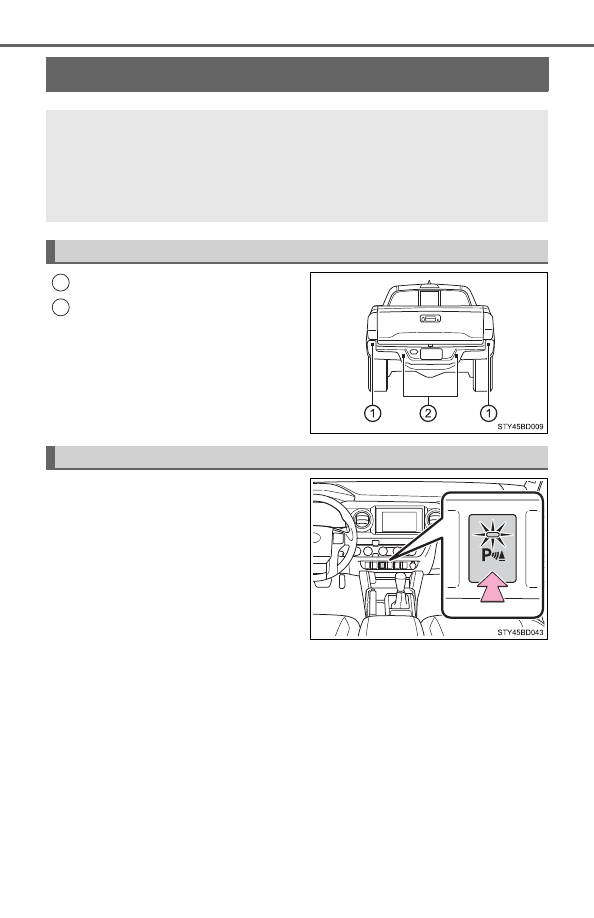
Intuitive parking assist

Rear corner sensors
Rear center sensors

Turns  the  intuitive  parking  assist
on/off

When on, the indicator light comes
on to inform the driver that the sys-
tem is operational.

: If equipped

The distance from your vehicle to nearby obstacles when paral-
lel  parking  or  maneuvering  into  a  garage  is  measured  by  the
sensors  and  communicated  via  the  multi-information  display
and buzzer. Always check the surrounding area when using this
system.

Types of sensors

1

2

Intuitive parking assist switch

285

4-5. Using the driving support systems

4

Dr

ivi

ng

When the sensor detects an obstacle, the direction of and the approx-
imate distance to the obstacle are displayed and the buzzer sounds.

Intuitive parking assist display

Rear corner sensor operation
Rear center sensor operation

Sensor operation and distance to an obstacle

The system operates when the vehicle approaches an obstacle, as
shown by the following table.

When 2 or more obstacles are detected simultaneously, the buzzer sys-
tem responds to the nearest zone.

Rear corner sensors

Rear center sensor

The distance display and buzzer

1

2

Approximate distance to obstacle

Display and buzzer

2.8 ft. (85 cm) to 2.0 ft. (60 cm)

Intermittent

2.0 ft. (60 cm) to 1.3 ft. (40 cm)

Fast intermittent

Less than 1.3 ft. (40 cm)

Continuously

Approximate distance to obstacle

Display and buzzer

5.9 ft. (180 cm) to 3.3 ft. (100 cm)

Intermittent

3.3 ft. (100 cm) to 2.5 ft. (75 cm)

Fast intermittent

2.5 ft. (75 cm) to 1.6 ft. (50 cm)

Very fast intermittent

Less than 1.6 ft. (50 cm)

Continuously

286

4-5. Using the driving support systems

When multiple obstacles are detected in front and behind the
vehicle at the same time

The buzzer will change in the following manner.

If an obstacle has been detected within 1.5 ft. (45 cm) of the front
or 2.8 ft. (85 cm)  in rear of the vehicle (a continuous buzzer  is
sounding), and a new obstacle is detected at the other end of the
vehicle, the buzzer will sound 7 times then 1 continuous buzzer.

If an obstacle has been detected within 1.5 ft. (45 cm) of the front
or 2.8 ft. (85 cm)  in rear of the vehicle (a continuous buzzer  is
sounding), and a new obstacle is detected in the same way at the
other  end  of  the  vehicle,  the  buzzer  will  sound  3  times  then  1
continuous buzzer.

Detection range of the sensors

Approximately 5.9 ft. (180 cm)
Approximately 2.8 ft. (85 cm)

The  diagram  shows  the  detection
range of the sensors. Note that the
sensors may not be able to detect
obstacles that are extremely close
to the vehicle.
The  range  of  the  sensors  may
change depending on the shape of
the object, etc.

1

2

287

4-5. Using the driving support systems

4

Dr

ivi

ng

The system can be operated when

The engine switch is in ON mode.

Intuitive parking assist function is on.

The vehicle speed is less than about 6 mph (10 km/h).

A shift position other than P is selected.

Sensor detection information

The  sensor’s  detection  areas  are  limited  to  the  areas  around  the  vehicle’
front and rear bumpers.

The following situations may occur during use.
• Depending on the shape of the object and other factors, the detection dis-

tance may shorten, or detection may be impossible.

• Detection may be impossible if static objects draw too close to the sen-

sor.

• There  will  be  a  short  delay  between  static  object  detection  and  display

(warning buzzer sounds). Even at low speeds, there is a possibility that
the object will come within 11.9 in. (30 cm) before the display is shown
and the warning buzzer sounds.

• It might be difficult to hear the buzzer due to the volume of the audio sys-

tem or air flow noise of the air conditioning system.

• It may be difficult to hear the sound of this system due to the buzzers of

other systems.

Objects which the system may not be properly detected

The shape of the object may prevent the sensor from detecting it. Pay partic-
ular attention to the following objects:

Wires, fences, ropes, etc.

Cotton, snow and other materials that absorb sound waves

Sharply-angled objects

Low objects

Tall objects with upper sections projecting outwards in the direction of your
vehicle

Situations in which the system may not operate properly

Certain  vehicle  conditions  and  the  surrounding  environment  may  affect  the
ability of a sensor to correctly detect objects. Particular instances where this
may occur are listed below.

There is dirt, snow, water drops or ice on a sensor. (Cleaning the sensors
will resolve this problem.)

A sensor is frozen. (Thawing the area will resolve this problem.) 
In especially cold weather, if a sensor is frozen the sensor display may be
displayed abnormally, or objects, such as a wall, may not be detected.

288

4-5. Using the driving support systems

On an extremely bumpy road, on an incline, on gravel, or on grass.

When  vehicle  horns,  vehicle  detectors,  motorcycle  engines,  air  brakes  of
large vehicles, the clearance sonar of other vehicles or other devices which
produce ultrasonic waves are near the vehicle

A sensor is coated with a sheet of spray or heavy rain.

If objects draw too close to the sensor.

When a pedestrian is wearing clothing that does not reflect ultrasonic waves
(ex. skirts with gathers or frills).

When objects that are not perpendicular to the ground, not perpendicular to
the vehicle traveling direction, uneven, or waving are in the detection range.

Strong wind is blowing

When driving in inclement weather such as fog, snow or a sandstorm

When  an  object  that  cannot  be  detected  is  between  the  vehicle  and  a
detected object

If an object such as a vehicle, motorcycle, bicycle or pedestrian cuts in front
of the vehicle or runs out from the side of the vehicle

If the orientation of a sensor has been changed due to a collision or other
impact

When equipment that may obstruct a sensor is installed, such as a towing
eyelet,  bumper  protector  (an  additional  trim  strip,  etc.),  bicycle  carrier,  or
snow plow

If the front of the vehicle is raised or lowered due to the carried load

If the vehicle cannot be driven in a stable manner, such as when the vehicle
has been in an accident or is malfunctioning

When a tire chains, compact spare tire or an emergency tire puncture repair
kit is used

When  a  sensor  or  the  area  around  a
sensor is extremely hot or cold.

289

4-5. Using the driving support systems

4

Dr

ivi

ng

Situations in which the system may operate even if there is no possibil-
ity of a collision

In  some  situations,  such  as  the  following,  the  system  may  operate  even
though there is no possibility of a collision.

When  driving  toward  a  banner,  flag,  low-hanging  branch  or  boom  barrier
(such as those used at railroad crossings, toll gates and parking lots)

When there is a rut or hole in the surface of the road

When driving on a metal cover (grating), such as those used for drainage
ditches

When driving up or down a steep slope

If  a  sensor  is  hit  by  a  large  amount  of  water,  such  as  when  driving  on  a
flooded road

There is dirt, snow, water drops or ice on a sensor. (Cleaning the sensors
will resolve this problem.)

A sensor is coated with a sheet of spray or heavy rain

When driving in inclement weather such as fog, snow or a sandstorm

When driving on a narrow road

When strong winds are blowing

290

4-5. Using the driving support systems

When  vehicle  horns,  vehicle  detectors,  motorcycle  engines,  air  brakes  of
large vehicles, the clearance sonar of other vehicles or other devices which
produce ultrasonic waves are near the vehicle

If the front of the vehicle is raised or lowered due to the carried load

If the orientation of a sensor has been changed due to a collision or other
impact

The vehicle is approaching a tall or curved curb

Driving close to columns (H-shaped steel beams, etc.) in multi-story parking
garages, construction sites, etc.

If the vehicle cannot be driven in a stable manner, such as when the vehicle
has been in an accident or is malfunctioning

When a tire chains, compact spare tire or an emergency tire puncture repair
kit is used

If a message is displayed on the multi-information display

P. 495

Customization

Settings (e.g. buzzer volume) can be changed.
(Customizable features 

P. 568)

Certification (Canada only)

This ISM device complies with Canadian ICES-001.

On  an  extremely  bumpy  road,  on  an
incline, on gravel, or on grass

291

4-5. Using the driving support systems

4

Dr

ivi

ng

WARNING

Cautions regarding the use of the system

There  is  a  limit  to  the  degree  of  recognition  accuracy  and  control  perfor-
mance that this system can provide, do not overly rely on this system. The
driver is always responsible for paying attention to the vehicle’ surroundings
and driving safely.

To ensure the system can operate properly

Observe the following precautions.
Failing to do so may result in the vehicle being unable to be driven safely
and possibly cause an accident.

Do not damage the sensors, and always keep them clean.

Do not attach a sticker or install an electronic component, such as a backlit
license plate (especially fluorescent type), fog lights, fender pole or wire-
less antenna near a radar sensor.

Do  not subject  the surrounding  area  of the  sensor  to a strong  impact.  If
subjected to an impact, have the vehicle inspected by your Toyota dealer.
If the front or rear bumper needs to be removed/installed or replaced, con-
tact your Toyota dealer.

Do not modify, disassemble or paint the sensors.

Do not attach a license plate cover.

Keep your tires properly inflated.

When to disable the function

In  the  following  situations,  disable  the  function  as  it  may  operate  even
though there is no possibility of a collision.

Failing to observe the warnings above.

A non-genuine Toyota suspension (lowered suspension, etc.) is installed.

Notes when washing the vehicle

Do not apply intensive bursts of water or steam to the sensor area.
Doing so may result in the sensor malfunctioning.

When using a high pressure washer to wash the vehicle, do not spray the
sensors directly, as doing so may cause a sensor to malfunction.

When using steam to clean the vehicle, do not direct steam too close to
the sensors as doing so may cause a sensor to malfunction.

292

4-5. Using the driving support systems

BSM (Blind Spot Monitor)

The Blind Spot Monitor is a system that has 2 functions;

The Blind Spot Monitor function
Assists the driver in making the decision when changing lanes

The Rear Cross Traffic Alert function
Assists the driver when backing up

These functions use same sensors.

BSM main switch

Pressing the switch turns the system on or off. When the switch is set to
on, the switch’s indicator illuminates and the buzzer sounds. Common
switch for Blind Spot Monitor function and Rear Cross Traffic Alert func-
tion.

Outside rear view mirror indicators

Blind Spot Monitor function: 
When a vehicle is detected in a blind spot of the outside rear view mir-
rors  or  approaching  rapidly  from  behind  into  a  blind  spot,  the  outside
rear view mirror indicator on the detected side will illuminate. If the turn
signal lever is operated toward the detected side, the outside rear view
mirror indicator will flash.
Rear Cross Traffic Alert function: 
When a vehicle approaching from the right or left at the rear of the vehi-
cle is detected, both outside rear view mirror indicators will flash.

: If equipped

Summary of the Blind Spot Monitor

1

2

293

4-5. Using the driving support systems

4

Dr

ivi

ng

Rear Cross Traffic Alert buzzer (Rear Cross Traffic Alert function
only)

When a vehicle approaching from the right or left rear of the vehicle is
detected, a buzzer sounds from behind the left-hand rear pillar.

The outside rear view mirror indicators visibility

When under strong sunlight, the outside rear view mirror indicator may be dif-
ficult to see.

Rear Cross Traffic Alert buzzer hearing

Rear Cross Traffic Alert function may be difficult to hear over noises such as
high audio volume.

When there is a malfunction in the Blind Spot Monitor system

If a system malfunction is detected due to any of the following reasons, warn-
ing messages will be displayed: (

P. 496)

There is a malfunction with the sensors

The sensors have become dirty

The outside temperature is extremely high or low

The sensor voltage has become abnormal

Certification for the Blind Spot Monitor system

For vehicles sold in the U.S.A.

FCC ID: OAYSRR2A
This device complies with part 15 of the FCC Rules. Operation is subject to
the following two conditions:
(1) This device may not cause harmful interference, and 
(2) this device must accept any interference received, including interference
that may cause undesired operation.
FCC Warning
Changes or modifications not expressly approved by the party responsible for
compliance could void the user’s authority to operate the equipment.

For vehicles sold in Canada

Applicable law: Canada 310
This device complies with Industry Canada licence-exempt RSS standard(s).
Operation is subject to the following two conditions: (1) this device may not
cause interference, and (2) this device must accept any interference, includ-
ing interference that may cause undesired operation of the device.
Frequency bands: 24.05 – 24.25 GHz
Output power: less than 20 milliwatts

3

294

4-5. Using the driving support systems

Droit applicable : Canada 310
Le  présent  appareil  est  conforme  aux  CNR  d’Industrie  Canada  applicables
aux appareils radio exempts de licence. L’exploitation est autorisée aux deux
conditions suivantes : (1) I’appareil ne doit pas produire de brouillage, et (2)
I’utilisateur  de  I’appareil  doit  accepter  tout  brouillage  radioélectrique  subi,
même si le brouillage est susceptible d’en compromettre le founctionnement.
Bandes de fréquences : 24.05 – 24.25 GHz
Puissance émise : Moins de 20 milliwatts

The Blind Spot Monitor function uses radar sensors to detect vehicles
that are traveling in an adjacent lane in the area that is not reflected in
the outside rear view mirror (the blind spot), and advises the driver of
the vehicles existence via the outside rear view mirror indicator.

WARNING

To ensure the system can operate properly

One Blind Spot Monitor sensor is installed inside the left and right side of
the vehicle rear bumper respectively. Observe the following to  ensure the
Blind Spot Monitor system can function correctly.

Do not subject the sensor or surrounding area on the bumper to a strong
impact. If the sensor moves even slightly off position, the system may mal-
function and vehicles that enter the detection area may not be detected. If
the sensor or surrounding area is subject to a strong impact, always have
the area inspected by your Toyota dealer.

Do not disassemble the sensor.

Do not attach accessories or stickers to the sensor or surrounding area on
the bumper.

Do not modify the sensor or surrounding area on the bumper.

Do not paint the rear bumper any color other than an official Toyota color.

The Blind Spot Monitor function

Keep  the  sensor  and  its  surrounding
area on the bumper clean at all times.

295

4-5. Using the driving support systems

4

Dr

ivi

ng

The areas that vehicles can be detected in are outlined below.
The  range  of  the  detection  area
extends to:

Approximately  11.5  ft.  (3.5  m)
from the side of the vehicle

The  first  1.6  ft.  (0.5  m)  from  the
side  of  the  vehicle  is  not  in  the
detection area

Approximately 9.8 ft. (3 m) from
the rear bumper
Approximately 3.3 ft. (1 m) for-
ward of the rear bumper

The Blind Spot Monitor function detection areas

1

2

3

WARNING

Cautions regarding the use of the system

The driver is solely responsible for safe driving. Always drive safely, taking
care to observe your surroundings.
The Blind Spot Monitor function is a supplementary function which alerts the
driver that a vehicle is present in the blind spot. Do not overly rely on the
Blind Spot Monitor function. The function cannot judge if it is safe to change
lanes, therefore over reliance could cause an accident resulting in death or
serious injury.
According  to  conditions,  the  system  may  not  function  correctly. Therefore
the driver’s own visual confirmation of safety is necessary.

296

4-5. Using the driving support systems

The Blind Spot Monitor function is operational when

The BSM main switch is set to on.

Vehicle speed is greater than approximately 10 mph (16 km/h)

The Blind Spot Monitor function will detect a vehicle when

A vehicle in an adjacent lane overtakes the vehicle.

Another vehicle enters the detection area when it changes lanes.

Conditions under which the system will not detect a vehicle

The Blind Spot Monitor function is not designed to detect the following types
of vehicles and/or objects:

Small motorcycles, bicycles, pedestrians, etc.

*

Vehicles traveling in the opposite direction

Guardrails, walls, signs, parked vehicles and similar stationary objects

*

Following vehicles that are in the same lane

*

Vehicles driving 2 lanes across from your vehicle

*

*

: Depending on conditions, detection of a vehicle and/or object may occur

Conditions under which the system may not function correctly

The Blind Spot Monitor function may not detect vehicles correctly in the fol-
lowing conditions:
• During bad weather such as heavy rain, fog, snow, etc.
• When ice or mud, etc., is attached to the rear bumper
• When driving on a road surface that is wet due to rain, standing water,

etc.

• When there is a significant difference in speed between your vehicle and

the vehicle that enters the detection area

• When a vehicle is in the detection area from a stop and remains in the

detection area as your vehicle accelerates

• When driving up or down consecutive steep inclines, such as hills, a dip

in the road, etc.

• When  multiple  vehicles  approach  with  only  a  small  gap  between  each

vehicle

• When vehicle lanes are wide, and the vehicle in the next lane is too far

away from your vehicle

• When the vehicle that enters the detection area is traveling at about the

same speed as your vehicle

• When towing anything such as trailer, boat, etc.
• When there is a significant difference in height between your vehicle and

the vehicle that enters the detection area

• Directly after the BSM main switch is set to on
• When items such as a bicycle carrier are installed on the rear of the vehi-

cle

297

4-5. Using the driving support systems

4

Dr

ivi

ng

Instances of the Blind Spot Monitor function unnecessarily detecting a vehi-
cle and/or object may increase under the following conditions:
• When there is only a short distance between your vehicle and a guardrail,

wall, etc.

• When there is only a short distance between your vehicle and a following

vehicle

• When vehicle lanes are narrow and a vehicle driving 2 lanes across from

your vehicle enters the detection area

• When items such as a bicycle carrier are installed on the rear of the vehi-

cle

The Rear Cross Traffic Alert functions when your vehicle is in reverse.
It can detect other vehicles approaching from the right or left rear of
the vehicle. It uses radar sensors to alert the driver of the other vehi-
cle’s existence through flashing the outside rear view mirror indicators
and sounding a buzzer.

The Rear Cross Traffic Alert function

Approaching vehicles

Detection areas

1

2

298

4-5. Using the driving support systems

The areas that vehicles can be detected in are outlined below.

To give the driver a more consistent time to react, the buzzer can alert
for faster vehicles from farther away.
Example:

WARNING

Cautions regarding the use of the system

There  is  a  limit  to  the  degree  of  recognition  accuracy  and  control  perfor-
mance that this system can provide, do not overly rely on this system. The
driver is always responsible for paying attention to the vehicle’s surround-
ings and driving safely. (

P. 295)

To ensure the system can operate properly

P. 294

The Rear Cross Traffic Alert function detection areas

Approaching vehicle

Speed

Approximate 
alert distance

Fast

18 mph (28 km/h)

65 ft. (20 m)

Slow

5 mph (8 km/h)

18 ft. (5.5 m)

1

299

4-5. Using the driving support systems

4

Dr

ivi

ng

The Rear Cross Traffic Alert function is operational when

The BSM main switch is set to on.

The shift lever is in R.

Vehicle speed is less than approximately 5 mph (8 km/h).

Approaching vehicle speed is between approximately 5 mph (8 km/h) and
18 mph (28 km/h).

Conditions under which the system will not detect a vehicle

The Rear Cross Traffic Alert function is not designed to detect the following
types of vehicles and/or objects.

Vehicles approaching from directly behind

Vehicles backing up in the parking space next to your vehicle

Guardrails, walls, signs, parked vehicles and similar stationary objects

*

Small motorcycles, bicycles, pedestrians, etc.

*

Vehicles moving away from your vehicle

Vehicles approaching from the parking spaces next to your vehicle

*

The distance between the sensor and approaching vehicle gets too close

*

: Depending on conditions, detection of a vehicle and/or object may occur.

Situations in which the system may not operate properly

The  RCTA  function  may  not  detect  vehicles  correctly  in  the  following  situa-
tions:

When the sensor is misaligned due to a strong impact to the sensor or its
surrounding area

When mud, snow, ice, a sticker, etc., is covering the sensor or surrounding
area on the position above the rear bumper

When driving on a road surface that is wet with standing water during bad
weather, such as heavy rain, snow, or fog

When  multiple  vehicles  are  approaching  with  only  a  small  gap  between
each vehicle

When a vehicle is approaching at high speed

When equipment that may obstruct a sensor is installed, such as a towing
eyelet,  bumper  protector  (an  additional  trim  strip,  etc.),  bicycle  carrier,  or
snow plow

Vehicles that the sensors cannot detect
due to obstructions


Content      ..     15      16      17      18     ..