Toyota bZ4X (2023 year). Manual in english - page 26
 

  Index      Toyota     Toyota bZ4X (2023 year). Manual in english


Search            copyright infringement  


Content      ..     24      25      26      27     ..


Toyota bZ4X (2023 year). Manual in english - page 26


417

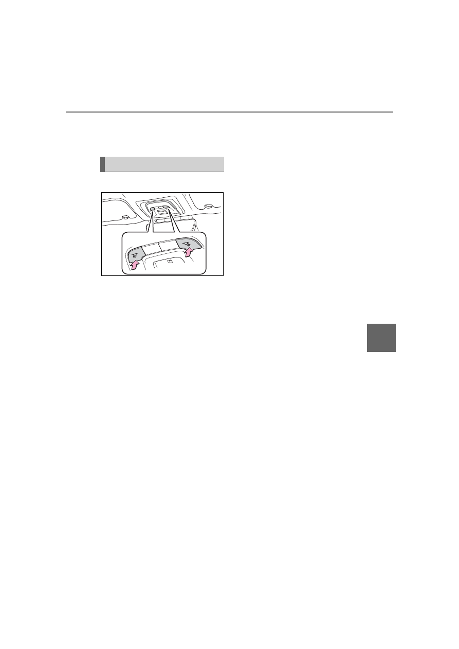
6-2. Using the interior lights

6

Interior

 featur

es

the opening/closing of the doors.
The rear interior light turn on/off 
together the front interior light.

Turns the lights on/off

Operating personal lights

418

6-3. Using the storage features

6-3.Using the storage features

Bottle holders (

P.420)

Card holders (

P.420)

Cup holders (

P.419)

Auxiliary box (if equipped) (

P.420)

Console box (

P.419)

Open tray (

P.420)

List of storage features

Location of the storage features

WARNING

Items that should not be left 

in the vehicle

Do not leave glasses, lighters or 

spray cans in the storage spaces, 

as this may cause the following 

when cabin temperature becomes 

high:

Glasses may be deformed by 

heat or cracked if they come 

into contact with other stored 

items.

Lighters or spray cans may 

explode. If they come into con-

tact with other stored items, the 

lighter may catch fire or the 

spray can may release gas, 

causing a fire hazard.

419

6-3. Using the storage features

6

Interior

 featur

es

1

Slide the lid as backward.

2

Lift the lid while pulling the 
lever to release the lock.

Console box lid

The lid can be slide forward/back-

ward.

Tray within console box

The tray can be removed by lifting 

the tray it out.

Front

Slide the lid as backward.

Rear

Pull down the armrest.

Console box

WARNING

Caution while driving

Keep the console box closed.

Injuries may result in the event of 

an accident or sudden braking.

NOTICE

To prevent damage to the 

console box

Do not apply excessive force to 

the armrest.

Cup holders

WARNING

Items unsuitable for the cup 

holders

Do not place anything other than 

cups or aluminum cans in the cup 

holders.

Other items may be thrown out of 

the holders in the event of an 

accident or sudden braking, caus-

ing injury. If possible, cover hot 

drinks to prevent burns.

420

6-3. Using the storage features

Front

Rear

Bottle holders

When storing a bottle, close the 

cap.

The bottle may not be stored 

depending on its size or shape.

Flip down the visor.

Press the lid to open the auxil-
iary box.

Bottle holders

NOTICE

Items that should be not 

stowed in the bottle holders

Do not place open bottles or glass 

and paper cups containing liquid 

in the bottle holders. The contents 

may spill and glasses may break.

Card holders

Auxiliary box (Vehicles 
without wireless charger)

Open tray

421

6-3. Using the storage features

6

Interior

 featur

es

Raise the hooks to use.

The cargo hooks are provided for 
securing loose items.

Upper hook (rope hook)

Upper hook (utility hook)

Lower hook

WARNING

Caution while driving

Observe the following precautions 

when putting items in the open 

tray. Failure to do so may cause 

items to be thrown out of the tray 

in the event of sudden braking or 

steering. In these cases, the items 

may interfere with pedal operation 

or cause driver distraction, result-

ing in an accident.

• Do not store items in the tray 

that can easily shift or roll out.

• Do not stack items in the tray 

higher than the edge of tray.

• Do not put items in the tray that 

may protrude over the edge of 

tray.

Luggage compart-

ment features

Cargo hooks

WARNING

When cargo hooks are not in 

use

To avoid injury, always return the 

hooks to their stowed positions 

when not in use.

NOTICE

To prevent damage to the 

upper hook (utility hook)

Do not hang any object heavier 

than 8 lb. (4 kg) on the upper 

hook (utility hook).

422

6-3. Using the storage features

Changing the deck board 
positions

Height of the deck floor can be 
changed by setting the deck 
board under the floor.

Upper

Lower

1

Pull up the tab to raise the 
deck board and move it 
toward you to remove.

2

Place the deck board through 
the groove and move for-
ward.

Setting the deck board 
upright

When taking out the tools, the 
deck board can be set upright.

When the back surface (resin sur-
face) of the deck board is facing up, 
flip it back to the original position.

1

Pull up the tab to raise the 
deck board and fold it for-
ward.

Deck board

423

6-3. Using the storage features

6

Interior

 featur

es

2

Deck board in a standing 
state, put the edge into the 
holes.

Pull up the tab to raise the deck 
board and fold it forward.

Warning reflector

Depending on the size and shape of 

the warning reflector case, you may 

not be able to store it.

Removing the luggage 
cover unit

1

Pull up the tab to raise the 
deck board and fold it for-
ward. (

P.422)

2

Take out the luggage cover 
unit.

WARNING

When operating the deck 

board

Do not place anything on the deck 

board when operating the board. 

Otherwise, your fingers may be 

caught or an accident may result 

causing injuries.

Caution while driving

Keep the deck board closed.

In the event of sudden braking, an 

accident may occur due to an 

occupant being struck by the deck 

board or the items stored under 

the deck board.

Deck under tray

WARNING

Caution while driving

Keep the deck board closed.

In the event of sudden braking, an 

accident may occur due to an 

occupant being struck by the deck 

board or the items stored under 

the deck board.

Luggage cover (if 
equipped)

424

6-3. Using the storage features

Installing the luggage cover

1

Compress the both ends of 
the luggage cover and insert 
into the recess to install.

2

Pull out the luggage cover 
and hook it onto the anchors.

Removing the luggage 
cover

1

Release the cover from the 
left and right anchors and 
allow it to retract.

2

Compress the end of the lug-
gage cover and lift the lug-
gage cover up.

Stowing the luggage cover 
unit

1

Pull up the tab to raise the 
deck board and fold it for-
ward. (

P.422)

2

To store the luggage cover 
unit, compress both ends 
until they lock.

1

Insert the left end of the lug-
gage cover unit into the 
groove on the left side of the 
deck.

2

Insert the right end of the lug-
gage cover unit into the 
groove on the right side of 
the deck side.

425

6-3. Using the storage features

6

Interior

 featur

es

WARNING

Luggage cover

When installing/stowing the lug-

gage cover, make sure that the 

luggage cover is securely 

installed/stowed. Failure to do 

so may result in serious injury in 

the event of sudden braking or a 

collision.

Do not place anything on the 

luggage cover. In the event of 

sudden braking or turning, the 

item may go flying and strike an 

occupant. This could lead to an 

unexpected accident, resulting 

in death or serious injury.

Do not allow children to climb 

on the luggage cover. Climbing 

on the luggage cover could 

result in damage to the luggage 

cover, possibly causing death or 

serious injury to the child.

426

6-4. Using the other interior features

6-4.Using the other interior features

*

: If equipped

1

Open

*

2

Close

*

*

: To stop the electronic sunshade 

partway, lightly press the either 
end of the switch.

The electronic sunshade can be 

operated when

The power switch is in ON.

Jam protection function for the 

electronic sunshade

If an object becomes jammed 

between the electronic sunshade 

and the sunshade frame while the 

electronic sunshade is closing, the 

electronic sunshade movement is 

stopped and the electronic sun-

shade is opened slightly.

When the jam protection function 

has operated, even if the 

“CLOSE” side of the switch is 

pressed again, the electronic sun-

shade will not move in the close 

direction until the reverse opera-

tion has stopped completely.

The electronic sunshade may 

operate in reverse if the electronic 

sunshade is subject to an impact 

due to the surroundings or the 

driving conditions.

When the electronic sunshade 

does not close normally

Perform the following initialization 

procedure.

1

Turn the power switch to ON.

2

Press and hold the “CLOSE” 

side of the switch.

It closes until it is near the fully 
closed position and then stops. After 
that, it operates in the opening 
direction then closes to the fully 
closed position.
If the switch is released at the incor-
rect time, the procedure will have to 
be performed again from the begin-
ning.
If the automatic opening and closing 
function does not work normally 
even after performing the operations 
above, have the vehicle inspected 
by your Toyota dealer.

Electronic sunshade

*

Use the overhead switches 
to operate the electronic 
sunshade.

Operating the electronic 
sunshade

WARNING

Observe the following precau-

tions.

Failure to do so may result in 

death or serious injury.

427

6-4. Using the other interior features

6

Interior

 featur

es

WARNING

Opening and closing the elec-

tronic sunshade

Check to make sure that all pas-

sengers do not have any part of 

their body in a position where it 

could be caught when the elec-

tronic sunshade is being oper-

ated.

Do not let a child operate the 

electronic sunshade. Closing 

the electronic sunshade on 

someone can cause death or 

serious injury.

Jam protection function

Never use any part of your body 

to intentionally activate the jam 

protection function.

The jam protection function may 

not work if something gets 

caught just before the electronic 

sunshade is fully closed. Also, 

the jam protection function is 

not designed to operate while 

the switch is being pressed. 

Take care so that your fingers, 

etc., do not get caught.

To prevent burns or injuries

Do not touch the area between 

the underside of the glass roof 

and the electronic sunshade. Your 

hand may get caught and you 

could injure yourself. Also, if the 

vehicle is left in direct sunlight for 

a long time, the underside of the 

panoramic moon roof could 

become very hot and could cause 

burns.

428

6-4. Using the other interior features

1

To set the visor in the forward 
position, flip it down.

2

To set the visor in the side 
position, flip down, unhook, 
and swing it to the side.

3

To use the side extender (if 
equipped), place the visor in 
the side position, then slide it 
backward.

Slide the cover to open.

The light turns on when the cover is 
opened.

Vanity lights

If the vanity lights remain on when 

the power switch is turned off, the 

lights will go off automatically after 

20 minutes.

Please use a power supply for 
electronic goods that use less 
than 12 VDC /10 A (power con-
sumption of 120 W).
When using electronic goods, 
make sure that the power con-
sumption of all the connected 
power outlets is less than 120 
W.
Open the lid.

The power outlet can be used 

when

The power switch is in ACC or ON.

When stopping the EV system

Disconnect electrical devices with 

charging functions, such as mobile 

battery packs.

If such devices are left connected, 

the EV system may not stop nor-

mally.

Other interior features

Sun visors

Vanity mirrors

NOTICE

To prevent 12-volt battery dis-

charge

Do not leave the vanity lights on 

for extended periods while the EV 

system is off.

Power outlet

429

6-4. Using the other interior features

6

Interior

 featur

es

The USB Type-C charging ports 
are used to supply 3 A of elec-
tricity at 5 V to external devices.
The USB Type-C charging ports 
are for charging only. They are 
not designed for data transfer or 
other purposes.

Depending on the external 
device, it may not charge prop-
erly. Refer to the manual 
included with the device before 
using a USB charging port.
Refer to “MULTIMEDIA 
OWNER’S MANUAL” for USB 
Type-A information.

Using the USB Type-C 
charging ports

Center console

Rear

The USB Type-C charging ports 

can be used when

The power switch is in ACC or ON.

Situations in which the USB 

Type-C charging ports may not 

operate correctly

If a device which consumes more 

than 3 A at 5 V is connected

If a device designed to communi-

cate with a personal computer, 

NOTICE

When power outlet is not in 

use

To avoid damaging the power out-

let, close the power outlet lid 

when the power outlet is not in 

use.

Foreign objects or liquids that 

enter the power outlet may cause 

a short circuit.

To prevent 12-volt battery dis-

charge

Do not use the power outlet lon-

ger than necessary when the EV 

system is off.

To prevent incorrect opera-

tion of the vehicle

When turning the power switch 

off, make sure to disconnect 

accessories designed for 

charging, such as portable char-

gers, power banks, etc. from the 

power outlets.
If such an accessory is left con-

nected, the following may occur:

The doors will not be able to be 

locked.

The opening screen will be dis-

played on the multi-information 

display.

The interior lights, instrument 

panel lights, etc. will illuminate.

USB Type-C charging 
ports

430

6-4. Using the other interior features

such as a USB memory device, is 

connected

If the connected external device is 

turned off (depending on device)

If the temperature inside the vehi-

cle is high, such as after the vehi-

cle has been parked in the sun

About connected external 

devices

Depending on the connected exter-

nal device, charging may occasion-

ally be suspended and then start 

again. This is not a malfunction.

A portable device can be 
charged by just placing Qi stan-
dard wireless charge compatible 
portable devices according to 
the Wireless Power Consortium, 
such as smartphones and 
mobile batteries, etc., on the 
charge area.
This function cannot be used 
with portable devices that are 
larger than the charging tray. 
Also, depending on the portable 
device, it may not operate as 
normal. Please read the opera-
tion manual for portable devices 
to be used.

The “Qi” symbol

The “Qi” symbol is a trademark 
of the Wireless Power Consor-
tium.

NOTICE

To prevent damage to the 

USB Type-C charging ports

Do not insert foreign objects into 

the ports.

Do not spill water or other liq-

uids into the ports.

Do not apply excessive force to 

or impact the USB Type-C 

charging ports.

Do not disassemble or modify 

the USB Type-C charging ports.

To prevent damage to exter-

nal devices

Do not leave external devices in 

the vehicle. The temperature 

inside the vehicle may become 

high, resulting in damage to an 

external device.

Do not push down on or apply 

unnecessary force to an exter-

nal device or the cable of an 

external device while it is con-

nected.

To prevent 12-volt battery dis-

charge

Do not use the USB Type-C 

charging ports for a long period of 

time with the EV system stopped.

Wireless charger (if 
equipped)

431

6-4. Using the other interior features

6

Interior

 featur

es

Name for all parts

Charging tray

Charging area

*

Operation indicator light

*

: Portable devices and wireless 

chargers contain charging coils. 
The charging coil in the wireless 
charger can be moved within the 
charge area near the center of 
the charging tray. If the charging 
coil inside a portable device is 
detected in the charge area, the 
charging coil inside the wireless 
charger will move toward it and 
start charging. If the charging coil 
inside a portable device moves 
outside of the charge area, 
charging will automatically stop.
If 2 or more portable devices are 
placed on the charging tray, their 
charging coils may not be prop-
erly detected and they may not 
be charged.

Using the wireless charger

1

Open the lid.

2

Place the portable device on 
the charging tray.

Place the charging side of the por-

table device down with the center of 

the device in the center of the 

charge area.
Depending on the portable device, 

the charging coil may not be 

located in the center of the device. 

In this case, place the portable 

device so that its charging coil is in 

the center of the charge area.
While charging, the operation indi-

cator light (orange) comes on.
If charging is not occurring, try plac-

ing the portable device as close to 

the center of the charging area as 

possible.
When charging is complete, the 

operation indicator light (green) 

comes on.

Recharging function

When charging is complete 
and after a fixed time in the 
charge suspension state, 
charging restarts.

When a portable device is 
moved significantly in the 
charge area, the charging coil 
is disconnected and charging 
is stopped momentarily. How-
ever, if there is a charging coil 
in the charge area, the 
charging coil inside the wire-
less charger will move toward 
it and then charging restarts.

432

6-4. Using the other interior features

Rapid charging function

The following portable 
devices support rapid 
charging.

• Portable devices compliant with 

WPC Ver1.2.4 and compatible 
with rapid charging

• iPhone’s with an iOS version that 

supports 7.5 W charging (iPhone 
8 and later models)

When a portable device that 
supports rapid charging is 
charged, charging automati-
cally switches to the rapid 
charging function.

Lighting conditions of operation indicator light

*1

:Charging power will not be output during standby. A metallic object will 

not be heated, if it is placed on the charging tray in this state.

*2

:Depending on the portable device, there are cases where the operation 

indicator light will continue being lit up orange even after the charging is 
complete.

The wireless charger is not working properly.

The following are situations in which the wireless charger does not 
work properly and how to deal with the possible causes.

Operation indicator light

Conditions

Charging tray 

side

Multimedia sys-

tem screen side

Turning off

Disappear

When the Wireless charger power 
supply is off

Green (comes 
on)

Gray

On Standby (charging possible 
state)

*1

When charging is complete

*2

Orange (comes 
on)

Blue

When placing the portable device on 
the charging area (detecting the por-
table device)

Charging


Content      ..     24      25      26      27     ..