Toyota GR Supra (2022 year). Manual in english - page 10
 

  Index      Toyota     Toyota GR Supra (2022 year). Manual in english


Search            copyright infringement  


Content      ..     8      9      10      11     ..


Toyota GR Supra (2022 year). Manual in english - page 10


148

3-1. CONTROLS

Display

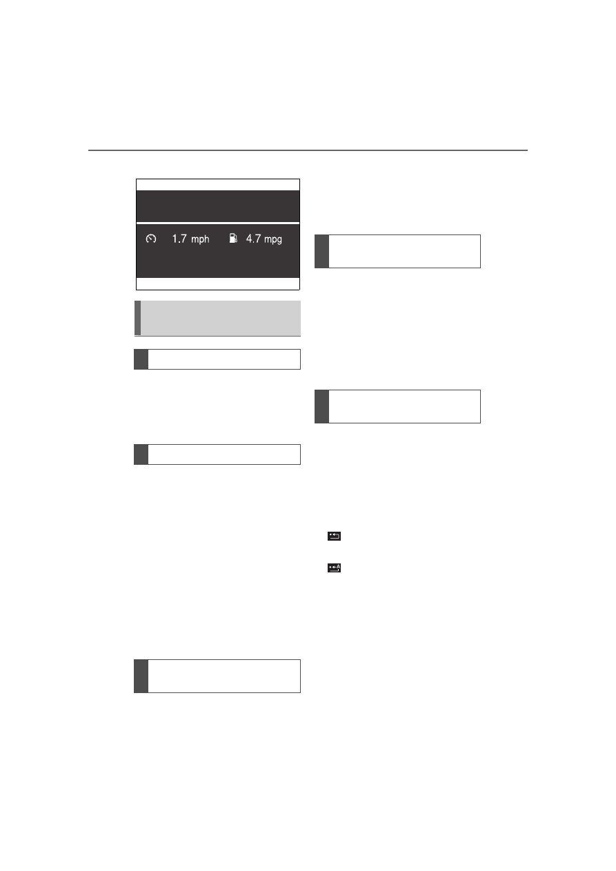
The Onboard Computer dis-
plays different vehicle data on 
the Control Display, such as 
average values.

Two types of Onboard Com-
puter are available on the Con-
trol Display:

"Onboard info": average val-
ues, such as the consump-
tion, are displayed. The 
values can be reset individu-
ally.

"Trip computer": the values 
deliver an overview of a cer-
tain distance and can be reset 
as often as necessary.

Via Toyota Supra Command:

1

"My Vehicle"

2

"Driving information"

3

"Onboard info" or "Trip com-
puter"

Via Toyota Supra Command:

1

"My Vehicle"

2

"Driving information"

3

"Onboard info"

4

"Consumption" or "Speed"

5

"OK"

Via Toyota Supra Command:

1

"My Vehicle"

2

"Driving information"

3

"Trip computer"

4

Move the Controller to the 
left, if needed.

"Reset": all values are 

reset.

"Automatic reset": all val-

ues are reset approx. 4 hours 
after the vehicle has come to 
a standhill.

5

If necessary, "OK"

Onboard Computer on the 
Control Display

Concept

General information

Calling up the Onboard 
Computer or trip computer

Resetting the Onboard 
computer

Resetting the trip com-
puter

149

3-1. CONTROLS

3

CON

T

ROLS

Depending on the vehicle speci-
fications, the current power out-
put and torque can be displayed 
on the control display.

The following information is dis-
played:

Torque.

Power.

Via Toyota Supra Command:

1

"My vehicle"

2

"Sport displays"

A speed limit can be set that 
when reached will cause a 
warning to be issued.

The warning is repeated if the 
vehicle speed exceeds the set 
speed limit again, after it has 
dropped below it by 3 mph/5 

km/h.

Via Toyota Supra Command:

1

"My Vehicle"

2

"Vehicle settings"

3

"Speed warning"

4

"Warning at:"

5

Turn the Controller until the 
desired speed is displayed.

6

Press the Controller.

Via Toyota Supra Command:

1

"My Vehicle"

2

"Vehicle settings"

3

"Speed warning"

4

"Speed warning"

Via Toyota Supra Command:

1

"My Vehicle"

2

"Vehicle settings"

3

"Speed warning"

4

"Select current speed"

The status can be displayed and 

Sport displays

Concept

Display on the Control Dis-
play

Overview

Displays

Speed warning

Concept

General information

Configuring the speed 
limit warning

Activating/deactivating the 
speed warning

Setting your current speed 
as the speed warning

Vehicle status

General information

150

3-1. CONTROLS

actions performed for several 
systems.

Via Toyota Supra Command:

1

"My vehicle"

2

"Vehicle status"

 "Tire Pressure Monitor": 

Status of the Tire Pressure 
Monitor, refer to page 280.

 "Engine oil level": Elec-

tronic engine oil level check, 
refer to page 295.

 "Vehicle messages": Vehi-

cle messages are stored in 
the background and can be 
displayed on the Control Dis-
play. Displaying stored vehi-
cle messages, refer to page 
134.

 "Service required": Dis-

playing service notifications, 
refer to page 141.

 "Remote maintenance 

Call": service request.

*

: if equipped

This system projects important 
information into the driver's field 
of vision, for instance the speed.

The driver can get information 
without averting his or her eyes 
from the road.

Follow the information on clean-
ing the Head-up Display, refer to 
page 327.

Via Toyota Supra Command:

1

"My vehicle"

2

"System settings"

3

"Displays"

4

"Head-up display"

5

"Head-up display"

The following information is dis-
played on the Head-up Display:

Speed.

Navigation instructions.

Opening the vehicle status

Information at a glance

Head-up Display*

Concept

General information

Overview

Switching on/off

Display

Overview

151

3-1. CONTROLS

3

CON

T

ROLS

Vehicle messages.

Selection list in the instrument 
cluster.

Driver assistance systems.

Some of this information is only 
displayed briefly as needed.

Various views are available for 
the Head-up Display.

Via Toyota Supra Command:

1

"My vehicle"

2

"System settings"

3

"Displays"

4

"Head-up display"

5

Select the desired setting.

The brightness is automatically 
adjusted to the ambient bright-
ness.

The basic setting can be 
adjusted manually.

Via Toyota Supra Command:

1

"My vehicle"

2

"System settings"

3

"Displays"

4

"Head-up display"

5

"Brightness"

6

Turn the Controller until the 
desired brightness is set.

7

Press the Controller.

When the low beams are 

switched on, the brightness of 
the Head-up Display can be 
additionally influenced using the 
instrument lighting.

Via Toyota Supra Command:

1

"My vehicle"

2

"System settings"

3

"Displays"

4

"Head-up display"

5

"Height"

6

Turn the Controller until the 
desired height is reached.

7

Press the Controller.

The height of the Head-up Dis-
play can also be stored using 
the memory function, refer to 
page 107.

The Head-up Display view can 
be rotated.

Via Toyota Supra Command:

1

"My vehicle"

2

"System settings"

3

"Displays"

4

"Head-up display"

5

"Rotation"

6

Turn the Controller until the 
desired setting is selected.

7

Press the Controller.

Selecting the view

Setting the brightness

Adjusting the height

Setting the rotation

152

3-1. CONTROLS

The visibility of the displays in 
the Head-up Display is influ-
enced by the following factors:

Seat position.

Objects on the cover of the 
Head-up Display.

Sunglasses with certain polar-
ization filters.

Wet roads.

Unfavorable light conditions.

If the image is distorted, have 
the basic settings checked by 
your Toyota dealer.

The windshield is part of the 
system.

The shape of the windshield 
makes it possible to display a 
precise image.

A film in the windshield prevents 
double images from being gen-
erated.

For this reason, it is strongly 
suggested to have the special 
windshield replaced by your 
Toyota dealer if necessary.

This chapter describes all stan-
dard, country-specific and 
optional features offered with 
the series. It also describes fea-
tures and functions that are not 
necessarily available in your 
vehicle, e.g., due to the selected 
options or country versions. This 
also applies to safety-related 
functions and systems. When 
using these functions and sys-
tems, the applicable laws and 
regulations must be observed.

The light switch element is 
located next to the steering 
wheel.

Visibility of the display

Special windshield

Lights

Vehicle features and 
options

Lights and lighting

Switches in the vehicle

153

3-1. CONTROLS

3

CON

T

ROLS

The low beams are switched on 
and off automatically depending 
on the ambient brightness, for 
instance in tunnels, in twilight or 
if there is precipitation.

A blue sky with the sun low on 
the horizon can cause the lights 

to be switched on.

If the low beams are switched 
on manually, the automatic 
headlight control is deactivated.

The LED in the button lights up.

The automatic headlight control 
cannot serve as a substitute for 
your personal judgment of light-
ing conditions.

For example, the sensors are 
unable to detect fog or hazy 
weather. In these situations, 
switch the light on manually.

If the driver's door is opened 
when the drive-ready state is 
switched off, the exterior lighting 
is automatically switched off 
after a period of time.

Symbol

Function

Lights off.

Daytime running lights.

Parking lights.

Automatic headlight 

control.

Adaptive light functions.

Low beams.

Instrument lighting.

Right roadside parking 

light.

Left roadside parking 

light.

Automatic headlight con-
trol

Concept

General information

Activating

Press the button on the 
light switch element.

The indicator light in the 
instrument cluster is 
illuminated when the 
low beams are 
switched on.

System limits

Parking lights, low beams 
and roadside parking 
lights

General information

154

3-1. CONTROLS

The parking lights can only be 
switched on in the low speed 
range.

The vehicle is illuminated on all 
sides.

Do not use the parking lights for 
extended periods; otherwise, 
they might drain the battery and 
it would then be impossible to 
switch on drive-ready state.

After the drive-ready state is 
switched on, the automatic 
headlight control will be acti-
vated.

The low beams illuminate when 
drive-ready state is switched on.

Press the button again to switch 
on the low beams when the 
standby state is switched on.

Depending on the country vari-
ant, the low beams can be 
switched off in the low speed 
range.

Depending on the surrounding 
conditions, the low beam head-
lights may not be able to be 
turned off.

When the vehicle is parked, a 
one-sided roadside parking light 
can be switched on.

Parking lights

General information

Switching on

Press the button on the 
light switch element.

The indicator light in the 
instrument cluster lights 
up.

Switching off

Press the button on the 
light switch element or 
switch on the 
drive-ready state.

Low beams

Switching on

Press the button on the 
light switch element.

The indicator light in the 
instrument cluster lights 
up.

Switching off

Press the button on the 
light switch element.

Roadside parking lights

155

3-1. CONTROLS

3

CON

T

ROLS

Switching off the roadside park-
ing light:

Depending on the equipment, 
the exterior lighting of the vehi-
cle can be set individually.

Via Toyota Supra Command:

1

"My Vehicle"

2

"Vehicle settings"

3

"Exterior lighting"

4

Select desired setting:

"Welcome lights"

Individual light functions are 
switched on for a limited time.

The low beams stay illuminated 
for a particular time if the high 
beams are switched on after the 
drive-ready state is switched off.

Via Toyota Supra Command:

1

"My Vehicle"

2

"Vehicle settings"

3

"Exterior lighting"

4

"Pathway lighting"

5

Select the desired setting.

The daytime running lights light 
up when drive-ready state is 
switched on.

In some countries, daytime run-
ning lights are mandatory, so it 
may not be possible to deacti-
vate the daytime running lights.

Via Toyota Supra Command:

1

"My Vehicle"

2

"Vehicle settings"

3

"Exterior lighting"

Button

Function

Right roadside 
parking light 
on/off.

Left roadside 
parking light 
on/off.

Press the button on the 
light switch element or 
switch on the 
drive-ready state.

Welcome lights and head-
light courtesy delay fea-
ture

Welcome lights

General information

Activating/deactivating

Headlight courtesy delay 
feature

General information

Setting the duration

Daytime running lights

General information

Activating/deactivating

156

3-1. CONTROLS

4

"Daytime running lamps"

The Automatic high-beam 
detects other traffic participants 
early on and automatically 
switches the high beams on or 
off depending on the traffic situ-
ation.

The Automatic high-beam 
ensures that the high beams are 
switched on, whenever the traf-
fic situation allows. In the low 
speed range, the high beams 
are not switched on by the sys-
tem.

The system responds to light 
from oncoming traffic and traffic 
driving ahead of you, and to 
ambient lighting, for instance in 
towns and cities.

The high beams can be 
switched on and off manually at 
any time.

1

 Press the button on the 

light switch element.

The LED in the button lights up.

2

Press and hold the button on 
the turn signal lever.

The headlights are automatically 
switched between low beams 
and high beams.

Driving interruption with acti-
vated Automatic high-beam: the 
Automatic high-beam remains 
activated when driving contin-
ues.

The Automatic high-beam is 
deactivated when manually 
switching the high beams on 
and off, refer to page 122.

To reactivate the Automatic 
high-beam, press the button on 
the turn signal lever.

Automatic high-beam

Concept

General information

Activating

The indicator light in the 
instrument cluster is 
illuminated when the 
low beams are 
switched on.

The blue indicator light 
in the instrument clus-
ter lights up when the 
system switches on the 
high beams.

157

3-1. CONTROLS

3

CON

TROLS

Press and hold the button on the 

turn signal lever.

The sensitivity of the Automatic 

High Beam Assistant can be 

adjusted.

• Setting at standstill only.

• Drive readiness is switched 

on.

• Light is turned off.

Push the turn signal lever to the 

front for approximately 10 sec-

onds.
A Check Control message is 

displayed. The system responds 

more sensitively.

Push the turn signal lever to the 

front again for approx. 10 sec-

onds or switch off the 

drive-ready state.

The sensitivity of the Automatic 

High Beam Assistant is reset to the 

factory settings.

The Automatic High Beam 

Assistant cannot replace the 

driver's personal judgment of 

when to use the high beams. In 

situation that require this, there-

fore dimming manually.
The system is not fully functional 

in the following situations, and 

driver intervention may be nec-

essary:

In very unfavorable weather 

conditions, such as fog or 

heavy precipitation.

When detecting poorly-lit road 

users such as pedestrians, 

cyclists, horseback riders and 

wagons; when driving close to 

train or ship traffic; or at ani-

Deactivate Automatic High 

Beam Assistant

Sensitivity of the Auto-

matic High Beam Assis-

tant

General information

WARNING

If adjustments have been made or 

the sensitivity has been modified, 

oncoming traffic may be momen-

tarily blinded. There is a risk of an 

accident. If adjustments have 

been made and the sensitivity has 

been modified, make sure that 

oncoming traffic is not momentar-

ily blinded. Switch off the high 

beams manually if required.

Functional requirements

Increase sensitivity

Resetting the sensitivity

System limits

158

3-1. CONTROLS

mal crossings.

In tight curves, on hilltops or 
in depressions, in crossing 
traffic or half-obscured 
oncoming traffic on highways.

In poorly-lit towns and cities 
or in the presence of highly 
reflective signs.

When the windshield in front 
of the interior mirror is fogged 
over, dirty or covered with 
stickers, etc.

The parking lights or low beams 
must be switched on to adjust 
the brightness.

Depending on the equipment 
version, interior lights, footwell 
lights and door entry lighting are 
automatically controlled.

To switch off permanently: press 
the button and hold for approx. 3 
seconds.

Instrument lighting

Functional requirement

Settings

Adjust the brightness 
with the thumbwheel.

Interior lights

General information

Overview

Buttons in the vehicle

Interior lights

Reading lights

Switching the interior 
lights on/off

Press the button.

Switching the reading 
lights on/off

Press the button.

159

3-1. CONTROLS

3

CON

T

ROLS

This chapter describes all stan-
dard, country-specific and 
optional features offered with 
the series. It also describes fea-
tures and functions that are not 
necessarily available in your 
vehicle, e.g., due to the selected 
options or country versions. This 
also applies to safety-related 
functions and systems. When 
using these functions and sys-
tems, the applicable laws and 
regulations must be observed.

Safety

Vehicle features and 
options

160

3-1. CONTROLS

1

Knee airbag

2

Front airbag, driver

3

Front airbag, front passenger

4

Curtain shield airbag

5

Side airbag

Front airbags help protect the 
driver and the front passenger 
by responding to frontal impacts 
in which safety belts alone 
would not provide adequate pro-
tection.

In the event of a side impact, the 
side airbag protects the side of 
the body in the chest, lap, and 
head area.

The knee airbag protects the 
legs in the event of a frontal 
impact.

The curtain shield airbag sup-
ports the head in the event of a 
side-on crash.

Airbags

Front airbags

Side airbag

Knee airbag

Curtain shield airbag

161

3-1. CONTROLS

3

CON

TROLS

Airbags are not triggered in 

every impact situation, for 

instance in less severe acci-

dents.

Keep a distance from the air-

bags.

Always grasp the steering 

wheel on the steering wheel 

rim. Hold your hands at the 3 

o'clock and 9 o'clock posi-

tions, to keep the risk of injury 

to your hands or arms as low 

as possible when the airbag is 

triggered.

Adjust seat and steering 

wheel so that hands can be 

crossed over the steering 

wheel. Select the settings so 

that the shoulder rests against 

the backrest when crossing 

the hands and the upper body 

is as far back as possible 

while still maintaining a com-

fortable grip on the steering 

wheel.

Make sure that the front pas-

senger is sitting correctly, i.e., 

keeps his or her feet and legs 

in the floor area and does not 

support them on the dash-

board.

Make sure that occupants 

keep their heads away from 

the side airbag.

There should be no addi-

tional persons, animals or 

objects between an airbag 

and a person.

Dashboard and windshield on 

the front passenger side must 

stay clear - do not attach 

adhesive labels or coverings 

and do not attach brackets or 

cables, for instance for GPS 

devices or mobile phones.

Do not apply adhesive materi-

als to the airbag cover panels, 

do not cover them or modify 

them in any way.

Do not use the cover of the 

front airbag on the front pas-

senger side as a storage 

area.

Do not attach slip covers, seat 

cushions or other objects to 

the front passenger seat that 

are not specifically suited for 

seats with integrated side air-

bags.

Protective effect

General information

Information on optimum 

effect of the airbags

WARNING

If the seat position is incorrect or 

the deployment area of the air-

bags is impaired, the airbag sys-

tem cannot provide protection as 

intended and may cause addi-

tional injuries due to triggering. 

There is a risk of injuries or dan-

ger to life. Follow the information 

on achieving the optimum protec-

tive effect of the airbag system.

162

3-1. CONTROLS

Do not hang pieces of cloth-

ing, such as jackets, over the 

backrests.

Never modify either the indi-

vidual components or the wir-

ing in the airbag system. This 

also applies to steering wheel 

covers, the dashboard, and 

the seats.

Do not remove the airbag sys-

tem.

Even when you follow all 

instructions very closely, injury 

from contact with the airbags 

cannot be fully ruled out in cer-

tain situations.
The ignition and inflation noise 

may lead to short-term and, in 

most cases, temporary hearing 

impairment in sensitive occu-

pants.
Vehicle modifications for a per-

son with disabilities may affect 

the air bag system; contact the 

Toyota dealer for further infor-

mation.
Warnings and information on the 

airbags are also found on the 

sun visors.

Functional readiness of 

the airbag system

Safety information

WARNING

Individual components can be hot 

after triggering of the airbag sys-

tem. There is a risk of injury. Do 

not touch individual components.

WARNING

Improperly executed work can 

lead to failure, malfunction or 

unintentional triggering of the air-

bag system. In the case of a mal-

function, the airbag system might 

not trigger as intended despite the 

accident severity. There is a risk 

of injuries or danger to life. Have 

the airbag system checked, 

repaired, dismantled and 

scrapped by your Toyota dealer.

Display in the instrument 

cluster

When drive-ready state is 

switched on, the warning 

light in the instrument 

cluster lights up briefly and 

thereby indicates the func-

tion readiness of the entire 

airbag system and the belt 

tensioners.

Malfunction

Warning light does not 

come on when 

drive-ready state is 

switched on.

The warning light lights 

up continuously.

163

3-1. CONTROLS

3

CON

TROLS

Have the system checked.

The airbags are not designed to 

be used in place of the seat 

belts.
The SRS front airbags and SRS 

knee airbags are designed to 

supplement the seat belts, not 

be used in place of them, to 

increase their effectiveness as 

an occupant protection device.

SRS is an acronym for Supplemen-

tal Restraint System

In the event of a collision, the 

seat belts restrain the occupants 

in their seats, but if the impact of 

the collision is especially 

severe, there is danger of an 

occupant’s head and chest con-

tacting the steering wheel, dash-

board and windshield. In this 

case, the SRS front airbags and 

SRS knee airbags deploy 

(inflate), instantly creating an air 

cushion to help reduce the 

impact on the occupants and 

restrain them from contacting 

the steering wheel, etc. with 

their head, chest and knees.
The SRS front air bags and SRS 

knee airbags deploy only when 

an impact exceeding a certain 

threshold is detected. In a colli-

sion, even if the impact is 

severe enough to cause the 

vehicle body to deform, the SRS 

airbags may not deploy if the 

impact of the collision is suffi-

ciently dispersed by the crash 

structures of the vehicle body. If 

the force of the collision does 

not cause the airbags to deploy, 

the seatbelts will protect the 

occupants.
When an airbag deploys, as it 

will inflate nearly instantly, it may 

impact an occupant and cause 

an injury, or the loud noise emit-

ted by ignition or deployment 

may cause temporary partial 

loss of hearing. Also, as an air-

bag and nearby parts will be 

extremely hot after the airbag 

deploys, touching them may 

cause burns. For these reasons, 

deployment of the airbags is not 

entirely risk free. Therefore, in 

order to reduce this risk, the air-

bags are designed to only 

deploy when additional reduc-

tion of the impact applied to the 

occupants in a collision is nec-

essary.

SRS front airbag/SRS knee 

airbag

WARNING

Wear the seatbelt correctly and sit 

with the correct posture.

WARNING

If you sit with your head too close 

to the steering wheel, when the 

SRS front airbag deploys, it may 

apply a very large impact to your 

body. Sit in the driver’s seat with 

the correct posture and keep an 

appropriate distance away from 

the steering wheel.


Content      ..     8      9      10      11     ..