Toyota Mirai (2022 year). Manual in english - page 6
 

  Index      Toyota     Toyota Mirai (2022 year). Manual in english


Search            copyright infringement  


Content      ..     4      5      6      7     ..


Toyota Mirai (2022 year). Manual in english - page 6


97

3-1. Instrument cluster

3

Vehicle

 statu

s information an

d in
dicator

s

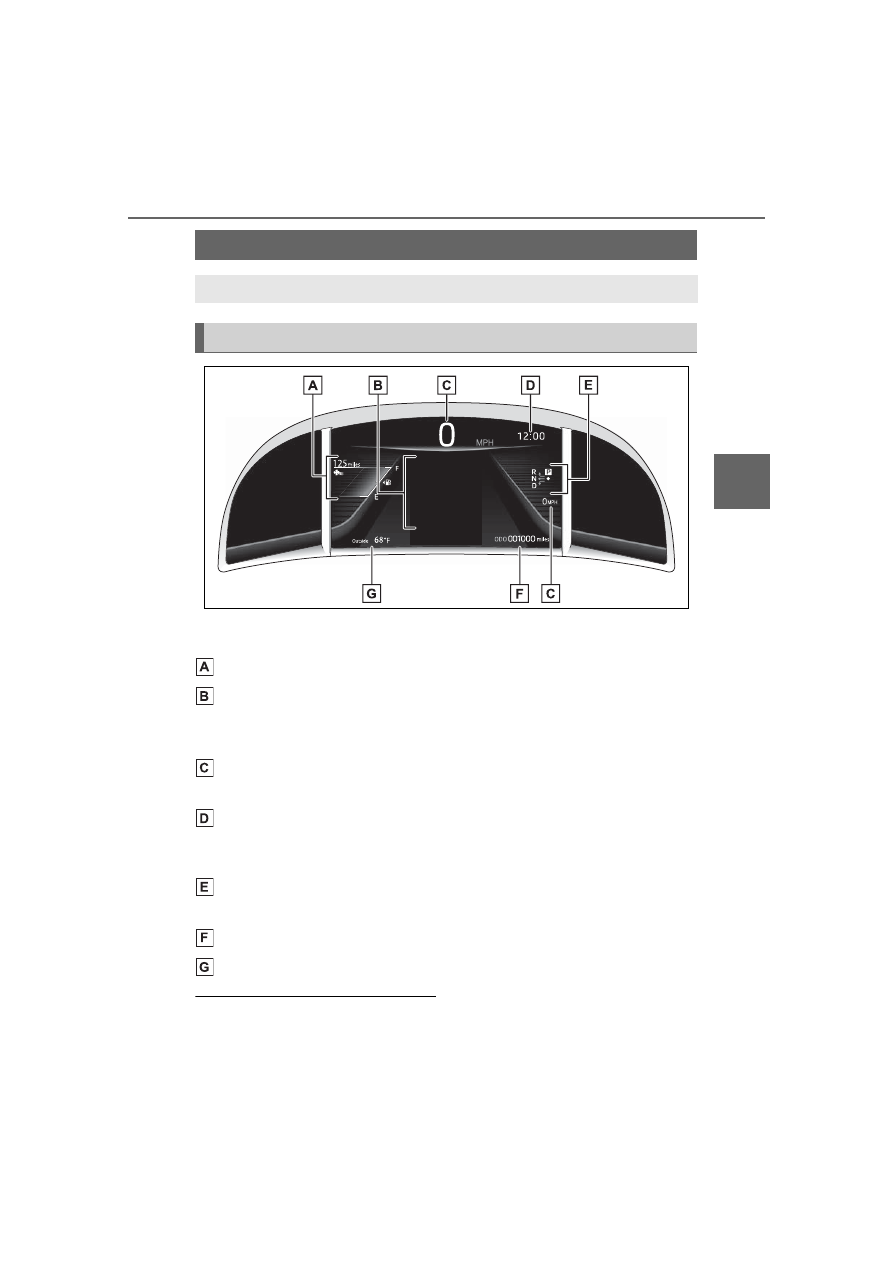
The units used on the meter and display may differ depending on the target 
region.

Fuel gauge/Driving range (

P.99)

Multi-information display

Presents the driver with a variety of driving-related data (

P.100)

Displays warning messages if a malfunction occurs (

P.451)

Speedometer

Displays the vehicle speed

Clock (

P.98)

Time displayed is linked to the multimedia system. For details, refer to 
“NAVIGATION AND MULTIMEDIA SYSTEM OWNER’S MANUAL”.

Shift position indicator

Displays the selected shift position (

P.178)

Odometer and trip meter (

P.98)

Outside temperature (

P.98)

The meters and display illumi-

nate when

The power switch is in ON.

Gauges and meters

The meters display various drive information.

Meter display

98

3-1. Instrument cluster

When changing driving mode

Background color of the multi-infor-

mation display is changed following 

the selected driving mode. (

P.313, 

314)

Clock settings screen

If “Clock :00” is displayed when 


is selected on the multi-information 
display, the system may be malfunc-
tioning. Have the vehicle inspected 
by your Toyota dealer.

Outside temperature display

In the following situations, the cor-

rect outside temperature may not 

be displayed, or the display may 

take longer than normal to 

change.

• When stopped, or driving at low 

speeds (less than 12 mph [20 

km/h])

• When the outside temperature 

has changed suddenly (at the 

entrance/exit of a garage, tunnel, 

etc.)

When “--” or “E” is displayed, the 

system may be malfunctioning.

Take your vehicle to your Toyota 

dealer.

Displays the outside temperature 

within the range of -40°F (-40°C) 

to 122°F (50°C).

When the outside temperature is 
approximately 37°F (3°C) or 
lower, the indicator 

 will flash 

for approximately 10 seconds, 
then stay on.

Liquid crystal display

P.100

Customization

Settings (e. g. meter display) can be 
changed on 

 screen of the multi-

information display. (

P.498)

Display items

Odometer

Displays the total distance the vehi-
cle has been driven.

Trip meter A/Trip meter B

Displays the distance the vehicle 
has been driven since the meter 
was last reset. Trip meters A and B 
can be used to record and display 
different distances independently.

Changing the display

Each time the “ODO/TRIP” 
switch is pressed, the displayed 
item will be changed. When the 
trip meter is displayed, pressing 
and holding the switch will reset 
the trip meter.

The brightness of the instrument 
panel lights can be adjusted.

Odometer and trip meter 
display

Instrument panel light 
control

99

3-1. Instrument cluster

3

Vehicle

 statu

s information an

d in
dicator

s

1

Brighter

2

Darker

Instrument cluster brightness 

adjustment

The instrument cluster brightness 

levels when the tail lights are on and 

off can be adjusted individually. 

However, when the surroundings 

are bright (daytime, etc.), turning on 

the tail lights will not change the 

instrument cluster brightness.

Fuel gauge

Displays the quantity of fuel 
remaining in the tank

Driving range

Displays the possible driving 
distance computed from the 
fuel consumption studied from 
the driving history and the 
current remaining amount of 
fuel.

When the air conditioning sys-
tem is operating, 

 is dis-

played below the driving 
range and this will be the driv-
ing range with the air condi-

tioning system on is 
displayed.

When the low fuel level warning 

light turns on

The low fuel level warning light turns 

on (

P.447) when the fuel gets low. 

In that case, refuel the vehicle.

Possible Driving Distance

The actual possible driving dis-

tance may differ as fuel consump-

tion changes, depending on 

driving environment (weather, traf-

fic, etc.) and conditions (sudden 

acceleration, air conditioning, 

etc.).

The driving range may shorten 

even when not driving due to 

power consumption by the sys-

tem.

The possible driving distance will 

be displayed as “--- miles (--- km)” 

in the following cases:

• When the remaining fuel is being 

calculated (short time).

• When the remaining fuel total 

reaches “E”.

• When a malfunction occurs where 

the possible driving distance can-

not be calculated.

Fuel gauge and driving 
range

100

3-1. Instrument cluster

Following information is dis-
played on the multi-information 
display.

Driving support system infor-
mation

Displays an image when the follow-
ing systems are operating and a 
menu icon other than 

 is 

selected:

• LTA (Lane Tracing Assist) 

(

P.223)

• Dynamic radar cruise control with 

full-speed range (

P.237)

• RSA (Road Sign Assist) (if 

equipped) (

P.234)

Information display area

A variety of information can be dis-
played by selecting a menu icon.
Additionally, warning or sugges-
tion/advice pop-up displays will be 
displayed in some situations.

Menu icons (

P.101)

The multi-information display is 

displayed when

The power switch is in ON.

When changing driving mode

Background color of the multi-infor-

mation display is changed following 

the selected driving mode. (

P.313, 

314)

Liquid crystal display

Small spots or light spots may 

appear on the display. This phenom-

enon is characteristic of liquid crys-

tal displays, and there is no problem 

continuing to use the display.

The multi-information display is 
operated using the meter control 
switches.

Scroll the screen

*

/switch the 

display

*

/move the cursor

Press: Enter/Set
Press and hold: Reset/Dis-

Multi-information dis-

play

The multi-information dis-
play is used to display fuel 
efficiency related informa-
tion and various types of 
driving-related information. 
The multi-information dis-
play can also be used to 
change the display settings 
and other settings.

Display contents

Changing the display

101

3-1. Instrument cluster

3

Vehicle

 s

ta

tu

s information an

d in
dicat

or

s

play customizable items

Return to the previous screen

Call sending/receiving and 
history display

Linked with the hands-free system, 
sending or receiving call is dis-
played. For details regarding the 
hands-free system, refer to the 
“NAVIGATION AND MULTIMEDIA 
SYSTEM OWNER’S MANUAL”.

*

: On screens where the screen can 

be scrolled and the display can 
be switched, a scroll bar or a 
round icon that shows the num-
ber of registered screens is dis-
played.

Information related to each icon 
can be displayed by selecting 
the icon with the meter control 
switches.

Some of the information may be 
displayed automatically depending 
on the situation.

Select to display fuel consump-
tion data in various forms.

Fuel Economy

Following information is dis-
played.

Current fuel economy

Displays the instantaneous current 
fuel Economy.

Average fuel economy

WARNING

Caution for use while driving

For safety, avoid operating the 

meter control switch while driving 

as much as possible, and do not 

look continuously at the multi-

information display while driving. 

Stop the vehicle and operate the 

meter control switch. Failure to do 

so may cause a steering wheel 

operation error, resulting in an 

unexpected accident.

Menu icons

Icon

Display

Driving information dis-
play (

P.101)

Driving support system 
information display 
(

P.104)

Audio system-linked dis-
play (

P.104)

Vehicle information dis-
play (

P.104)

Settings display 
(

P.105)

Warning message dis-
play (

P.106)

Driving information dis-
play

102

3-1. Instrument cluster

To reset the average fuel economy 
display, press and hold the 


meter control switch.

The average fuel economy dis-
play can be changed in 

(

P.105)

Average fuel economy (after 
start)

Displays the average fuel con-
sumption since fuel cell system 
start.

Average fuel economy (after 
refuel)

Displays the average fuel con-
sumption since the vehicle was 
refueled.

Fuel cell system indicator

Charge area

Shows regeneration

*

 status. 

Regenerated energy will be used to 
charge the traction battery.

Eco area

Shows that the vehicle is being 
driven in an Eco-friendly manner.By 
keeping the indicator needle within 
Eco area, more Eco-friendly driv-
ing can be achieved.

Power area

Shows that an Eco-friendly driving 
range is being exceeded (during full 
power driving, etc.)

*

: When used in this manual, 

“regeneration” refers to the con-
version of energy created by the 
movement of the vehicle into 
electrical energy.

In the following situation, the 
fuel cell system indicator does 
not operate.

“READY” indicator is not illu-
minated.

The shift lever is in a range 
other than D or Br mode.

ECO Accelerator Guid-
ance/Eco Score

Displays a reference operation 
range for using the accelerator 
pedal according to driving condi-
tions, and a score result that 
evaluates the current driving 
status.

ECO Accelerator Guidance

Eco Score

ECO Accelerator Guidance

103

3-1. Instrument cluster

3

Vehicle

 statu

s information an

d in
dicator

s

ECO area

Shows that the vehicle is being 
driven in an Eco-friendly manner.

Power area

Shows that an Eco-friendly driving 
range is being exceeded (during full 
power driving, etc.).

Current acceleration

Reference operation range

A zone is displayed in blue under 
the Eco area which can be used as 
a reference operation range for 
using the accelerator pedal accord-
ing to driving conditions such as 
starting off and cruising.
The ECO Accelerator Guidance 
display changes according to the 
driving status, such as when start-
ing off or cruising.
It is easier to drive in an Eco-
friendly manner by driving accord-
ing to the display showing the 
accelerator pedal operations and 
staying within the reference opera-
tion range.

Eco Score

The following 3 Eco driving meth-
ods are evaluated in 5 levels: 
Smooth start-off acceleration, driv-
ing without sudden acceleration, 
and smooth stopping. When the 

vehicle is stopped, an Eco score 
out of 100 points will be displayed.

Score result

Eco start status

Eco cruise status

Eco stop status

How to read the bar display:

After starting off, Eco Score display 
does not start until the vehicle 
speed exceeds approximately 19 
mph (30km/h).
The Eco Score is reset each time 
the vehicle starts off to start a new 
evaluation.
When the fuel cell system stops, 
the current total score result is dis-
played.

*

*

: The score result is displayed only 

when “Eco Score” is selected for 
“Trip Summary”. (

P.105)

Score

Bar display

Unrated

Low

High

104

3-1. Instrument cluster

ECO Accelerator Guidance/Eco 

Score will not operate when

The ECO Accelerator Guidance/Eco 

Score will not operate in the follow-

ing situations:

The fuel cell system indicator is 

not operating.

The vehicle is being driven using 

the dynamic radar cruise control 

with full-speed range.

Driving support system 
information display

Select to display the operational 
status of the following systems:

LTA (Lane Tracing Assist) 
(

P.223)

Dynamic radar cruise control 
with full-speed range 
(

P.237)

Navigation system-linked 
display (if equipped)

Select to display the following 
navigation system-linked infor-
mation.

Route guidance

Compass display (north-up 
display/heading-up display)

Select to enable selection of an 
audio source or track on the dis-
play.

Drive information

2 items that are selected using 
the “Drive Info Items” setting 
(average speed, distance and 
total time) can be displayed ver-
tically.
The displayed information 
changes according to the “Drive 
Info Type” setting (since the sys-
tem was started or between 
resets). (

P.105)

Use the displayed information as a 
reference only.
Following items will be displayed.

“Trip”

• “Average Speed”: Displays the 

average vehicle speed since fuel 
cell system start

*

• “Distance”: Displays the distance 

driven since fuel cell system start

*

• “Total Time”: Displays the elapsed 

time since fuel cell system start

*

*

: These items are reset each time 

the fuel cell system stops.

“Total”

• “Average Speed”: Displays the 

average vehicle speed since the 
display was reset

*

• “Distance”: Displays the distance 

driven since the display was 
reset

*

• “Total Time”: Displays the elapsed 

time since the display was reset

*

*

: To reset, display the desired item 

Driving support system 
information display

Audio system-linked dis-
play

Vehicle information dis-
play

105

3-1. Instrument cluster

3

Vehicle

 statu

s information an

d in
dicator

s

and press and hold 

.

Energy monitor

P.111

Tire inflation pressure

Displays inflation pressure of 
each tire.

Meter display settings that 
can be changed

Language

Select to change the language on 
the multi-information display.

Units

Select to change the units of mea-
sure displayed.

 (Driving information dis-

play settings)

Select to set up the following items.
• Fuel cell system
Select to enable/disable the ECO 
Accelerator Guidance (

P.102).

• Fuel Economy
Select to change the display on 
Fuel Economy (

P.101).

 (Audio settings)

Select to enable/disable 


screen.

 (Vehicle information dis-

play settings)

• Display Contents
Select to set up the following items.

Energy monitor:
Select to enable/disable the Energy 
monitor (

P.111)

• Drive Info Type
Select to change the drive informa-
tion type display between trip and 
total. (

P.104).

• Drive Info Items
Select to set the items on the upper 
and lower side of the drive informa-
tion screen from three items, aver-
age speed, distance and total time.

Trip Summary

Select to set the items displayed 
when the power switch is turned off.

Pop-Up Display

Select to enable/disable pop-up 
displays for each relevant system.

Multi-information display off

Select to turn the multi-information 
display off.
To turn the multi-information display 
on again, press any of the meter 
control switches.

Default Settings

Select to reset the meter display 
settings.

Suspension of the settings dis-

play

In the following situations, opera-

tion of the settings display will be 

temporarily suspended.

• When a warning message 

appears on the multi-information 

display

• When the vehicle begins to move

Settings for functions not 

equipped to the vehicle are not 

displayed.

When a function is turned off, the 

Settings display

106

3-1. Instrument cluster

related settings for that function 

are not selectable.

Select to display warning mes-
sages and measures to be 
taken if a malfunction is 
detected. (

P.451)

Displays suggestions to the 
driver in the following situations. 
To select a response to a dis-
played suggestion, use the 
meter control switches.

Suggestion to turn on the 
headlights

If the headlight switch is in other 
than 

 or 

, and the vehicle 

speed is 3 mph (5 km/h) or 
higher for a certain amount of 
time when the surroundings are 
dark, a suggestion message will 
be displayed.

Suggestion to turn off the 
headlights

If the headlights are left on for a 
certain amount of time after the 
power switch has been turned 
off, a suggestion message will 

be displayed.
When the headlight switch is in 
the AUTO position: The mes-
sage asking if you wish to turn 
the headlights off is displayed. 
To turn the headlights off, select 
“Yes”.

If the driver’s door is opened after 
the power switch is turned off, this 
suggestion message will not be dis-
played.

Customization

The suggestion function can be 

turned on/off. (Customizable fea-

tures: 

P.498)

NOTICE

During setting up the display

To prevent 12-volt battery dis-

charge, ensure that the fuel cell 

system is operating while setting 

up the display features.

Warning message display

Suggestion function

107

3-1. Instrument cluster

3

Vehicle

 statu

s information an

d in
dicator

s

*

: If equipped

Illustrations used in this text are intended as examples, and may differ from 
the image that is actually displayed by the head-up display.

Navigation system-linked display area (if equipped)

Displays the following items which are linked to the navigation system:
• Route guidance to destination
• Street name
• Compass (heading-up display)

Driving support system display area (

P.110)

Speed limit/RSA (Road Sign Assist) display area (if equipped)

Displays the following items:
• Speed limit of the current road (linked to the navigation system) (U.S.A. 

only)

• RSA (Road Sign Assist) display (

P.234)

Outside temperature display area

Displayed when the power switch is turned to ON or when the low outside 
temperature indicator is flashing.

Driving information display area

Head-up display

*

The head-up display projects a variety of driving-related infor-
mation and the operating state of the driving support systems 
on the windshield.

System components

108

3-1. Instrument cluster

Displays the following items:
• Speedometer
• Shift position (

P.178)

• Br mode (

P.178)

Fuel cell system indicator display area (

P.111)

Head-up display will operate 

when

The power switch is in ON.

When using the head-up dis-

play

The head-up display may seem 

dark or hard to see when viewed 

through sunglasses, especially 

polarized sunglasses. Adjust the 

brightness of the head-up display or 

remove your sunglasses.

Street name display

Only street names which are 

included in the map data will be dis-

played.

Outside temperature display

When the ambient temperature is 

approximately 37°F (3°C) or 

lower, the low outside temperature 

indicator will flash for approxi-

mately 10 seconds and the out-

side temperature display will turn 

off. In this case, the display will be 

displayed again when the outside 

temperature becomes approxi-

mately 41°F (5°C) or higher.

In the following situations, the cor-

rect outside temperature may not 

be displayed, or the display may 

take longer than normal to 

change:

• When stopped, or driving at low 

speeds (less than 12 mph [20 

km/h])

• When the outside temperature 

has changed suddenly (at the 

entrance/exit of a garage, tunnel, 

etc.)

When “--” or “E” is displayed, the 

system may be malfunctioning. 

Take your vehicle to your Toyota 

dealer.

WARNING

When using the head-up dis-

play

Check that the position and 

brightness of the head-up dis-

play image does not interfere 

with safe driving. Incorrect 

adjustment of the image’s posi-

tion or brightness may obstruct 

the driver’s view and lead to an 

accident, resulting in death or 

serious injury.

Do not continuously look at the 

head-up display while driving as 

you may fail to see pedestrians, 

objects on the road, etc., ahead 

of the vehicle.

NOTICE

Head-up display projector

Do not place any drinks near 

the head-up display projector. If 

the projector gets wet, electrical 

malfunctions may result.

NOTICE

Do not place anything on or put 

stickers onto the head-up dis-

play projector. 

Doing so could interrupt head-

up display indications.

109

3-1. Instrument cluster

3

Vehicle

 s

ta

tu

s information an

d in
dicat

or

s

Enabling/disabling the 
head-up display

Press the “HUD” switch.

Changing settings of the 
head-up display

The following settings can be 
changed on 

 of the multi-

information display. (

P.498)

Brightness and vertical posi-
tion of the head-up display

Select to adjust the brightness or 
vertical position of the head-up dis-
play.

Fuel cell system indicator

Select to enable/disable the fuel 
cell system indicator.

Display content

Select to enable/disable the follow-
ing items:
• Route guidance to destina-

tion/street name (vehicles with 

navigation system)

• Driving support system display

*

• Compass (heading-up display) 

(vehicles with navigation system)

• Audio system operation status

*

: Make sure to enable this display 

when using the driving support 
systems

Display angle

Enabling/disabling of the head-

up display

If the head-up display is disabled, it 

will remain disabled when the power 

switch is turned off then back to ON.

Display brightness

The brightness of the head-up dis-
play can be adjusted on 

 of the 

multi-information display. Also, it is 
automatically adjusted according to 
the ambient brightness.

Head-up display automatic 

position adjustment (if 

equipped)

If the display position is recorded 

into memory, the head-up display 

will be automatically adjusted to the 

desired position. (

P.136)

When the 12-volt battery is dis-

connected

The customize settings of the head-

up display will be reset.

Do not touch the inside of the 

head-up display projector or 

thrust sharp edges or the like 

into the projector. 

Doing so could cause mechani-

cal malfunctions.

Using the head-up display

NOTICE

When changing the settings 

of the head-up display

To prevent 12-volt battery dis-

charge, ensure that the fuel cell 

system is operating while the 

changing the settings of the head-

up display.

110

3-1. Instrument cluster

Displays the operational status 
of the following systems:

LTA (Lane Tracing Assist) 
(

P.223)

Dynamic radar cruise control 
with full-speed range 
(

P.237)

Details of content displayed on the 
head-up display may differ from 
that displayed on the multi-informa-
tion display. For details, refer to the 
explanation of each system.

Pop-up displays for the following 
systems will be displayed when 
necessary.

Driving support systems

Displays a warning/sugges-
tion/advice message or the 
operating state of a relevant 
system.

PCS (Pre-Collision System) 
(

P.212)

Parking Support Brake func-
tion (for static objects) (if 
equipped) (

P.278)

Brake Override System 
(

P.162)

Drive-Start Control (

P.167)

Details of content displayed on the 
head-up display may differ from 
that displayed on the multi-informa-
tion display. For details, refer to the 

explanation of each system.

/

 icons

These icons are linked to the 
multi-information display

: Master warning icon

Displayed when a warning mes-
sage is displayed on the multi-infor-
mation display. (

P.451)

: Information icon

Displayed when a suggestion pop-
up display (

P.106) or advice pop-

up display is displayed on the multi-
information display.

Warning message

Some warning messages are 
displayed when necessary, 
according to certain conditions.

Details of content displayed on the 
head-up display may differ from 
that displayed on the multi-informa-
tion display.

Audio system operation 
status

Displayed when an audio 
remote control switch on the 
steering wheel is operated.

Hands-free system status

Displayed when the hands-free 
system is operated.

When a pop-up display is dis-

played

When a pop-up display is displayed, 

a current display may no longer be 

displayed. In this case, the display 

will return after the pop-up display 

disappears.

Driving support system 
display area

Pop-up display

111

3-1. Instrument cluster

3

Vehicle

 statu

s information an

d in
dicator

s

Charge area

Eco area

Power area

Displayed content is the same as 
that displayed on the meter (fuel 
cell system indicator). For details, 
refer to P.102.

Multi-information display

Multimedia display

“MENU” button

Meter control switches

The energy monitor can be used 
to check the vehicle drive status, 
fuel cell system operation status 
and energy regeneration status.

Display procedure

Multi-information display

Press 

 or 

 of the meter 

Fuel cell system indicator

Energy monitor/con-

sumption screen/air 

purification screen

The state of the fuel cell 
system can be viewed on 
the multi-information dis-
play and multimedia dis-
play (12.3-inch display 
only).

System components

Energy monitor

112

3-1. Instrument cluster

control switches on the steering 
wheel and select 

, press 


or 

 of the meter control 

switches and select the energy 
monitor.

Multimedia display (12.3-inch 
display only)

1

Select 

 on the Toyota 

multi-operation touch 
(

P.353).

2

Select 

 on the screen.

Displaying a screen in full screen 

(

P.354)

Display

When energy is flowing, an 
arrow appears to show the 
direction of the flow of energy.

When energy is not flowing, an 
arrow is not displayed.
Green: Shows that the electrical 
energy is charged or recovered.
Yellow: Shows that the electrical 
energy is used.
Red: Shows that the power of the 
fuel cell system is used.

Multi-information display

The figure shows all the arrows for 
the purpose of this explanation, but 
the actual contents of the display 
will differ.

Fuel cell system

Traction battery

Front tires

Rear tires

Multimedia display (12.3-inch 
display only) (when displayed 
full screen)

The figure shows all the arrows for 
the purpose of this explanation, but 
the actual contents of the display 
will differ.

Fuel cell system

Electric motor (traction 
motor)

Traction battery


Content      ..     4      5      6      7     ..