4A–FE engine is an in–line, 4–cylinder, 1.6 liter DOHC 16–valve engine. Manual - part 13


  Index      Manuals     4A–FE engine is an in–line, 4–cylinder, 1.6 liter DOHC 16–valve engine. Repair Manual


Search            


Content   ..  11  12  13  14   ..


4A–FE engine is an in–line, 4–cylinder, 1.6 liter DOHC 16–valve engine. Manual - part 13


B. Inspect cam lobes

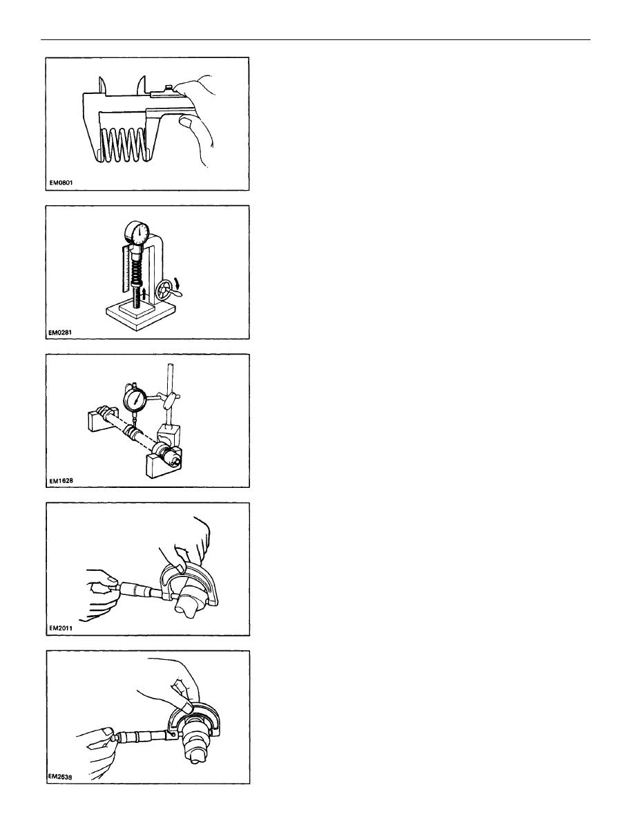
Using a micrometer, measure the cam lobe height.
Standard cam lobe height:

Intake 

35.210 – 35.310 mm

(1.3862 –1. 3902 in.)

Exhaust 

34.910 – 35.010 mm

(1.3744 – 1.3783 in.)

Minimum cam lobe height:

Intake 

34.81 mm (1.3705 in.)

Exhaust 

34.51 mm (1.3587 in.)

If the cam lobe height is less than minimum, replace the
camshaft.

C. Inspect camshaft journals

Using a micrometer, measure the journal diameter.
Journal diameter:

Exhaust No.1 

24.949 – 24.965 mm

(0.9822 – 0.9829 in.)

Others 

22.949 – 22.965 mm

(0.9035 – 0.9041 in.)

If the journal diameter is not as specified, check the oil
clearance.

10. INSPECT CAMSHAFTS AND BEARINGS
A. Inspect camshaft for runout

(a) Place the camshaft on V–blocks.
(b) Using a dial indicator, measure the circle runout at

the center journal.

Maximum circle runout: 0.04 mm (0.0016 in.)

If the circle runout is greater than maximum, replace the
camshaft.

(c) Using a spring tester, measure the tension of the

valve spring at the specified installed length.

Installed tension:

143 – 155 N (14.6 – 15.8 kgf, 32.2 – 34.8 lbf )

at 34.7 mm (1.366 in.)

If the installed tension is not as specified, replace the
valve spring.

(b) Using a vernier caliper, measure the free length of

the valve spring.

Free length: 43.8 mm (1.724 in.)

If the free length is not as specified, replace the valve
spring.

ENGINE MECHANICAL

Cylinder Head (4A–FE)

EM–98

E. Inspect camshaft gear spring

Using a vernier caliper, measure the free distance be-
tween the spring ends.
Free distance: 17.0 –17.6 mm (0.669 – 0.693 in.)
If the free distance is not as specified, replace the gear
spring.

F. Inspect camshaft journal oil clearance

(a) Clean the bearing caps and camshaft journals.
(b) Place the camshafts on the cylinder head.
(c) Lay a strip of Plastigage across each of the camshaft

journals.

D. Inspect camshaft bearings

Check the bearings for flaking and scoring.
If the bearings are damaged, replace the bearing caps
and
cylinder head as a set.

(d) Install the bearing caps.

(See step 3 on pages 

EM–105

 to 107)

Torque: 13 N–m (130 kgf–cm, 9 ft–lbf)

NOTICE: Do not turn the camshaft.

(e) Remove the bearing caps.

ENGINE MECHANICAL

Cylinder Head (4A–FE)

EM–99

H. Inspect camshaft gear backlash

(a) Install the camshafts without installing the exhaust

camshaft sub–gear.
(See step 3 on pages 

EM–105

 to 107)

(b) Using a dial indicator, measure the backlash.
Standard backlash: 0.020 – 0.200 mm

(0.0008 – 0.0079 in.)

Maximum backlash: 0.30 mm (0.0188 in.)

If the backlash is greater than maximum, replace the
camshafts.

11. INSPECT VALVE LIFTERS AND LIFTER BORES

(a) Using a caliper gauge, measure the lifter bore diame-

ter of the cylinder head.

Lifter bore diameter: 

28.005 – 28.026 mm
(1.1026 –1.1034 in.)

G. Inspect camshaft thrust clearance

(a) Install the camshafts.

(See step 3 on pages 

EM–105

 to 107)

(b) Using a dial indicator, measure the thrust clearance

while moving the camshaft back and forth.

Standard thrust clearance:

Intake 

0.030 – 0.085 mm

(0.0012 – 0.0033 in.)

Exhaust 

0.035 – 0.090 mm

(0.0014 – 0.0035 in.)

Maximum thrust clearance: 

0.11 mm (0.0043 in.)

If the thrust clearance is greater than maximum, replace
the camshaft. If necessary, replace the bearing caps and
cylinder head as a set.

(f) Measure the Plastigage at its widest point.
Standard oil clearance: 0.035 – 0.072 mm

(0.0014 – 0.0028 in.)

Maximum oil clearance: 0.10 mm (0.0039 in.)

If the oil clearance is greater than maximum, replace the
camshaft. If necessary, replace the bearing caps and
cylinder head as a set.
(g) Completely remove the Plastigage.

ENGINE MECHANICAL

Cylinder Head (4A–FE)

EM–100

12. INSPECT INTAKE AND EXHAUST MANIFOLDS

Using precision straight edge and feeler gauge, mea-
sure the surface contacting the cylinder head for warp-
age.
Maximum warpage:

Intake 0.20 mm (0.0079 in.)
Exhaust 0.30 mm (0.0118 in.)

If warpage is greater than maximum, replace the man-
ifold.

(c) Subtract the lifter diameter measurement from

the lifter bore diameter measurement.

Standard oil clearance: 0.020 – 0.051 mm

(0.0008 – 0.0020 in.)

Maximum oil clearance: 0.07 mm (0.0028 in.)
If the oil clearance is greater than maximum, re-
place the
lifter. If necessary, replace the cylinder head.

(b) Using SST, tap in a new gasket until its surface is

flush with the upper edge of the cylinder head
cover.

SST 09550–10012 (09552–10010, 09560–10010)
(c) Apply a light coat of IMP grease to the gasket lip.

(b) Using a micrometer, measure the lifter diameter.
Lifter diameter: 27.975 – 27.985 mm

(1.1014 –1.1018 in.)

13. IF NECESSARY, REPLACE SPARK PLUG TUBE

GASKET
(a) Using a screwdriver, pry out the gasket.

ENGINE MECHANICAL

Cylinder Head (4A–FE)

EM–101

ASSEMBLY OF CYLINDER HEAD

(See page 

EM–81

)

HINT:

Thoroughly clean all parts to be assembled.

Before installing the parts, apply new engine oil
to all
sliding and rotating surfaces.

Replace all gaskets and oil seals with new
ones.

1. INSTALL SPARK PLUG TUBES

HINT: When using a new cylinder head, spark plug
tubes must be installed.
(a) Apply adhesive to the spark plug tube hole of the

cylinder head.

Adhesive: Part No. 08833–00070, THREE BOND 1324

or equivalent

(b) Using a press, press in a new spark plug tube un-

til there is 46.8 – 47.6 mm (1.843 –1.874 in.)
protruding from the cylinder head.

NOTICE: Avoid tapping a new spark plug tube in

too far by measuring the amount of protrusion

while pressing.

2. INSTALL VALVES

(a) Using SST, push in a new oil seal.
SST 09201–41020

HINT: The intake valve oil seal is brown and the
exhaust valve oil seal is black.

ENGINE MECHANICAL

Cylinder Head (4A–FE)

EM–102

(c) Using SST, compress the valve spring and place the

two keepers around the valve stem.

SST 09202–70010

3. INSTALL VALVE LIFTERS AND SHIMS

(a) Install the valve lifter and shim.
(b) Check that the valve lifter rotates smoothly by hand.

(b) Install the following parts:

(1) Valve
(2) Spring seat
(3) Valve spring
(4) Spring retainer

(d) Using a plastic–faced hammer, lightly tap the

valve stem tip to assure proper fit.

ENGINE MECHANICAL

Cylinder Head (4A–FE)

EM–103

(c) Apply a light coat of engine oil on the threads and

under the heads of the cylinder head bolts.

(d) Install the plate washer to each cylinder head

bolt.

(e) Using SST, install and uniformly tighten the ten

cylinder head bolts in several passes in the se-
quence shown.

SST 09205–16010
Torque: 60 N–m (610 kgf–cm, 44 ft–lbf)

HINT: Cylinder head bolts are in length of 90 mm
(3.54 in.) and 108 mm (4.25 in.). Install the 90 mm
(3.54 in.) bolts (A) in intake manifold side posi-
tions. Install the 108 mm (4.25 in.) bolts (B) in ex-
haust manifold side positions.

INSTALLATION OF CYLINDER HEAD

(See page 

EM–81

)

1. INSTALL CYLINDER HEAD

(a) Place a new cylinder head gasket in position on the

cylinder block.

NOTICE: Be careful of the installation direction.
(b) Place the cylinder head in position on the cylinder

head gasket.

(b) Install the following parts:

(1) Camshaft gear spring
(2) Camshaft sub–gear
(3) Wave washer

HINT: Align the pins on the gears with the gear
spring ends.

2. ASSEMBLE EXHAUST CAMSHAFT

(a) Mount the hexagon wrench head portion of the

camshaft in a vise.

NOTICE: Be careful not to damage the camshaft.

ENGINE MECHANICAL

Cylinder Head (4A–FE)

EM–104

A. Install exhaust camshaft

(a) Apply MP grease to the thrust portion of the

camshaft.

(b) Place the intake camshaft so the knock pin is located

slightly counterclockwise from the vertical
axis of the camshaft.

HINT: The above angle allows the No.1 and No.3 cylin-
der cam lobes of the exhaust camshaft to push their
valve lifters evenly.

3. INSTALL CAMSHAFTS

NOTICE: Since the thrust clearance of the camshaft
is small, the camshaft must be kept level while it is

being installed. If the camshaft is not kept level, the

portion of the cylinder head receiving the shaft
thrust may crack or be damaged, causing the cam-
shaft to seize or break. To avoid this, the following
steps should be carried out.

(d) Insert service bolts (A) and (13) into the service

hole of the camshaft sub–gear.

(e) Using a screwdriver, align the holes of the cam-

shaft drive gear and sub–gear by turning cam-
shaft sub–gear clockwise, and install a service
bolt (C).

NOTICE: Be careful not to damage the camshaft.

(c) Remove any old packing (FIPG) material.
(d) Apply seal packing to the cylinder head as shown

in the illustration.
Seal packing: Part No. 08826–00080 or

equivalent

(c) Using snap ring pliers, install the snap ring.

ENGINE MECHANICAL

Cylinder Head (4A–FE)

EM–105


Content   ..  11  12  13  14   ..