4A–FE engine is an in–line, 4–cylinder, 1.6 liter DOHC 16–valve engine. Manual - part 11


  Index      Manuals     4A–FE engine is an in–line, 4–cylinder, 1.6 liter DOHC 16–valve engine. Repair Manual


Search            


Content   ..  9  10  11  12   ..


4A–FE engine is an in–line, 4–cylinder, 1.6 liter DOHC 16–valve engine. Manual - part 11


REMOVAL OF CYLINDER HEAD

(See page 

EM–81

)

1. DISCONNECT CABLE FROM NEGATIVE TERMINAL

OF BATTERY
CAUTION: Work must be started after approx. 20

seconds or longer from the time the ignition switch is

turned to the ”LOCK” position and the negative (–)

terminal cable is disconnected from the battery.

2. DRAIN ENGINE COOLANT (See page 

CO–6

)

3. (A/T)

DISCONNECT THROTTLE CABLE FROM THROTTLE
BODY

4. DISCONNECT ACCELERATOR CABLE FROM

THROTTLE BODY

5. REMOVE AIR CLEANER CAP AND HOSE

(See step 6 on page 

EM–185

)

6. REMOVE ENGINE UNDER COVERS
7. REMOVE SUSPENSION LOWER CROSSMEMBER

(See step 24 on page 

EM–189

)

8. REMOVE FRONT EXHAUST PIPE

(See step 25 on page 

EM–189

)

9. REMOVE DISTRIBUTOR (See page 

IG–20

)

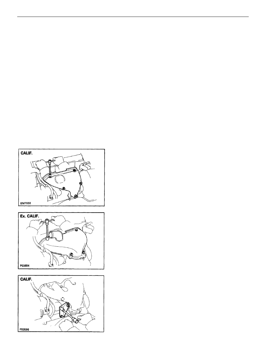
10. REMOVE EXHAUST MANIFOLD

(a) Remove the five (CALIF.) or four (Ex. CALIF.) bolts

and upper heat insulator.

(b) Remove the three (CALIF.) or two (Ex. CALIF.) bolts

and manifold stay.

ENGINE MECHANICAL

Cylinder Head (4A–FE)

EM–82

11. REMOVE WATER OUTLET

(a) Disconnect the upper radiator hose from the water

outlet.

(b) Remove the two bolts and water outlet.

(d) Remove the three bolts and lower heat insulator

from the exhaust manifold.

(c) Remove the two bolts, three nuts, exhaust manifold

and gasket.

ENGINE MECHANICAL

Cylinder Head (4A–FE)

EM–83

12. REMOVE WATER INLET AND INLET HOUSING

(a) Disconnect the following connectors:

Water temperature sender gauge connector

Water temperature sensor connector

(b) Disconnect the following hoses:

(1) Lower radiator hose
(2) Inlet pipe water hose
(3) Auxiliary air valve water by–pass hose
(4) Heater water hose
(5) Two EVAP BVSV vacuum hoses

(c) Remove the bolt, two nuts, the water inlet and inlet

housing assembly.

(b) Loosen the bolt holding the PS pump to the PS

pump bracket.

(c) Remove the bolt holding the PS pump to the PS

drive belt adjusting strut, and disconnect the drive
belt from the PS pump pulley.

(d) Disconnect the PS pump from the adjusting strut.

15. REMOVE THROTTLE BODY

(See steps 6, 8 and 9 on pages 

FI–188

 and 189)

16. REMOVE DELIVERY PIPE AND INJECTORS

(See steps 2 to 6 on page 

FI–156

)

13. DISCONNECT VACUUM HOSES

(a) Vacuum sensor hose from gas filter on intake manifold
(b) Brake booster vacuum hose from intake manifold
(c) Three A/C vacuum hoses from ASV on intake manifold
(d) A/C vacuum hose from air pipe

14. REMOVE PS PUMP WITHOUT DISCONNECTING

HOSES
(a) Disconnect the following hoses:

(1) Air hose from air pipe
(2) Air hose from intake manifold

ENGINE MECHANICAL

Cylinder Head (4A–FE)

EM–84

18. DISCONNECT ENGINE WIRE FROM NO.3 TIMING

BELT COVER
(a) Disconnect the following connectors and wire:

Alternator connector

Alternator wire

Oil pressure switch connector

A/C compressor connector

(b) Remove the bolt.
(c) Disconnect the wire clamp from the wire bracket,

and disconnect the engine wire from the timing belt
cover.

19. DISCONNECT ENGINE WIRE FROM INTAKE

MANIFOLD
(a) Disconnect the following connectors:

EGR VSV connector

(CALIF. only)
EGR gas temperature sensor connector

Vacuum sensor connector

(b) Disconnect the wire clamp from the vacuum pipe.
(c) Remove the three bolts, and disconnect the engine

wire from the intake manifold.

20. REMOVE VACUUM PIPE, EGR VACUUM

MODULATOR AND EGR VSV
(a) Disconnect the following hoses:

(1) Two vacuum hoses from EGR valve
(2) Vacuum hose from EGR VSV

17. REMOVE ACV

(a) Disconnect the air hose from the air pipe.
(b) Remove the bolt, nut and ACV.
(c) Remove the O–ring from the ACV.

(b) Remove the two nuts, the vacuum pipe, vacuum

modulator and VSV assembly.

ENGINE MECHANICAL

Cylinder Head (4A–FE)

EM–85

(b) Disconnect the PCV hose from the PCV valve on the

cylinder head.

(c) Remove the seven bolts, two nuts, intake manifold

and gasket.

22. REMOVE AIR PIPE

(a) Disconnect the following hoses:

(1) Water inlet pipe hose
(2) Fuel return hose (from fuel filter)

23. REMOVE INTAKE MANIFOLD

(a) Remove the two bolts and manifold stay.

21. REMOVE EGR VALVE

Remove the two nuts, EGR valve and gasket.

(b) Remove the two nuts and air pipe.

ENGINE MECHANICAL

Cylinder Head (4A–FE)

EM–86

25. DISCONNECT TIMING BELT FROM CAMSHAFT

TIMING PULLEY
(See steps 2 and 4 to 15 on pages 

EM–33

 to 36)

NOTICE:

Support the timing belt, so the meshing of the
crankshaft timing pulley and timing belt does not
shift.

Be careful not to drop anything inside the timing
belt. cover.

Do not allow the belt to come into contact with oil,
water or dust.

26. REMOVE CAMSHAFT TIMING PULLEY

(See step 16 on page 

EM–36

)

27. REMOVE FAN BELT ADJUSTING BAR

Remove the two bolts and adjusting bar.

28. REMOVE ENGINE HANGERS

Remove the bolt and engine hanger. Remove the two
engine hangers.

29. REMOVE PS DRIVE BELT ADJUSTING STRUT

Remove the two bolts and adjusting strut.

30. REMOVE CAMSHAFTS

NOTICE: Since the thrust clearance of the camshaft is

small, the camshaft must be kept level while it is

being removed. If the camshaft is not kept level, the
portion of the cylinder head receiving the shaft thrust

may crack or be damaged, causing the camshaft to

seize or break. To avoid this, the following steps

should be carried out.

A. Remove intake camshaft

(a) Set the intake camshaft so the knock pin is slightly

above the top of the cylinder head.

HINT: The above angle allows the No.1 and No.3 cylinder
cam lobes of the intake camshaft to push their valve
lifters evenly.

24. REMOVE CYLINDER HEAD COVER

Remove the three cap nuts, grommets, head cover and
gasket.

ENGINE MECHANICAL

Cylinder Head (4A–FE)

EM–87

(c) Secure the intake camshaft sub–gear to the drive

gear with a service bolt.

Recommended service bolt:

Thread diameter 6 mm
Thread pitch 1.0 mm
Bolt length 16 – 20 mm (0.63 – 0.79 in.)

HINT: When removing the camshaft, make sure that the
torsional spring force of the sub–gear has been elimi-
nated by the above operation.

B. Remove exhaust camshaft

(a) Set the intake camshaft so the knock pin is located

slightly counterclockwise from the vertical axis of
the camshaft.

HINT: The above angle allows the No. 1 and No. 3
cylinder cam lobes of exhaust camshaft to push their
valve lifters evenly.

HINT: If the camshaft is not being lifted out straight
and level, reinstall the bearing cap with the two bolts.
Then alternately loosen and remove the bearing cap bolts
with the camshaft gear pulled up.
NOTICE: Do not pry on or attempt to force the

camshaft with a tool or other object.

(d) Uniformly loosen and remove the eight bearing cap

bolts in several passes in the sequence shown.

(e) Remove the four bearing caps and camshaft.

(b) Remove the two bolts and front bearing cap.

ENGINE MECHANICAL

Cylinder Head (4A–FE)

EM–88

HINT: If the camshaft is not being lifted out straight
and level, reinstall the No.3 bearing cap with the two
bolts. Then alternately loosen and remove the two bear-
ing cap bolts with the camshaft gear pulled up.
NOTICE: Do not pry on or attempt to force the

camshaft with a tool or other object.

31. DISASSEMBLE EXHAUST CAMSHAFT

(a) Mount the hexagon wrench head portion of the

camshaft in a vise.

NOTICE: Be careful not to damage the camshaft.

(b) Insert service bolts (A) and (B) into the service

holes of the camshaft sub–gear.

(c) Using a screwdriver, turn the sub–gear clockwise,

and remove the service bolt (C).

NOTICE: Be careful not to damage the camshaft.

(b) Remove the two bolts, front bearing cap and oil

seal.

NOTICE: If the front bearing cap is not removable by

hand, do not try to remove by force but leave as it is

without bolts.

(c) Uniformly loosen and remove the eight bearing cap

bolts in several passes in the sequence shown.

(d) Remove the four bearing caps and camshaft.

ENGINE MECHANICAL

Cylinder Head (4A–FE)

EM–89


Content   ..  9  10  11  12   ..