4A–FE engine is an in–line, 4–cylinder, 1.6 liter DOHC 16–valve engine. Manual - part 14
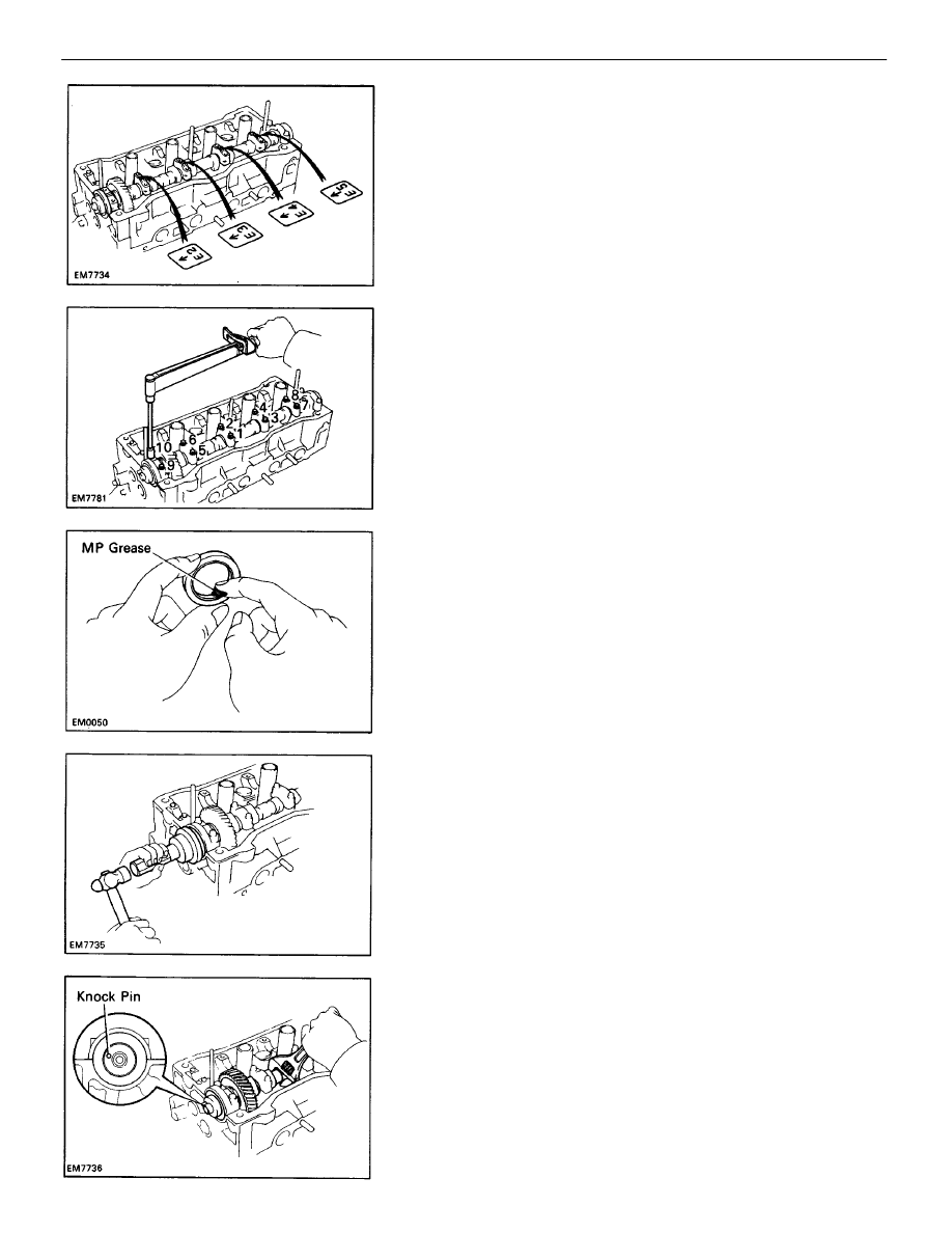
(f) Apply a light coat of engine oil on the threads and
under the heads of the bearing cap bolts.
(g) Install and uniformly tighten the ten bearing cap
bolts in several passes in the sequence shown.
Torque: 13 N–m (130 kgf–cm, 9 ft–lbf)
B. Install intake camshaft
(a) Set the intake camshaft so the knock pin is slightly
above the top of the cylinder head.
(i) Using SST, tap in the oil seal.
SST 09223–46011
(e) Install the five bearing caps in their proper loca-
tions.
(h) Apply MP grease to a new oil seal lip.
–
ENGINE MECHANICAL
Cylinder Head (4A–FE)
EM–106