Toyota FJ Cruiser (GSJ 10, 15 series). Instruction - part 416


  Index      Toyota     Toyota FJ Cruiser (model GSJ 10, 15 series) - service repair instruction 2007 year


Search            copyright infringement  


Content   ..  414  415  416  417   ..


Toyota FJ Cruiser (GSJ 10, 15 series). Instruction - part 416


MT–10

RA61F MANUAL TRANSMISSION  –  MANUAL TRANSMISSION ASSEMBLY

MT

19. REMOVE FLYWHEEL HOUSING SIDE COVER

(a) Remove the flywheel housing side cover from the 

cylinder block.

20. REMOVE NO. 1 CLUTCH HOUSING COVER (See 

page 

CL-16

)

21. REMOVE CLUTCH RELEASE CYLINDER ASSEMBLY 

(See page 

CL-16

)

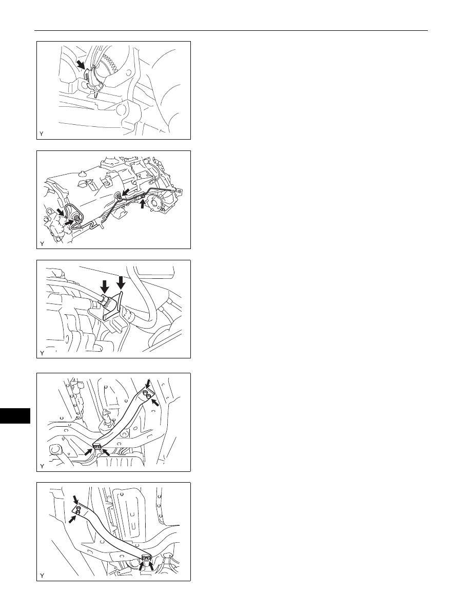
22. REMOVE ACCUMULATOR TO FLEXIBLE HOSE 

TUBE
(a) Using SST, disconnect the hose tube. (for 

accumulator side)
SST

09023-00101

(b) Remove the 3 nuts and disconnect the hose tube.

(c) Using SST, disconnect the hose tube. (for flexible 

hose side)
SST

09023-00101

(d) Remove the clip 

23. REMOVE CLUTCH ACCUMULATOR ASSEMBLY (See 

page 

CL-19

)

24. SUPPORT MANUAL TRANSMISSION WITH 

TRANSFER
(a) Support the manual transmission with a 

transmission jack.

25. REMOVE FRONT SUSPENSION MEMBER BRACKET 

LH
(a) Remove the 4 bolts and remove the front 

suspension member bracket LH.

26. REMOVE FRONT SUSPENSION MEMBER BRACKET

(a) Remove the 4 bolts and remove the front 

suspension member bracket RH.

F050352

C135783

C135784

C129541

C129542

RA61F MANUAL TRANSMISSION  –  MANUAL TRANSMISSION ASSEMBLY

MT–11

MT

27. REMOVE NO. 3 FRAME CROSSMEMBER SUB-

ASSEMBLY
(a) Remove the 4 bolts from the No. 3 frame 

crossmember sub-assembly.

(b) Remove the 4 nuts and 4 bolts and remove the No. 

3 frame crossmember sub-assembly.

28. REMOVE REAR NO. 1 ENGINE MOUNTING 

INSULATOR
(a) Remove the 4 bolts and engine mounting insulator 

rear from the manual transmission.

29. DISCONNECT CONNECTOR

(a) Tilt down the transmission.
(b) Disconnect the 2 transfer indicator switch 

connectors.

(c) Disconnect the speedometer sensor connector.
(d) Disconnect the back-up light switch connector.

30. DISCONNECT WIRE HARNESS

31. REMOVE MANUAL TRANSMISSION WITH 

TRANSFER
(a) Remove the 9 bolts.
(b) Separate and remove the manual transmission.

32. REMOVE MANUAL TRANSMISSION CASE COVER 

SUB-ASSEMBLY
(a) Remove the 3 bolts and 2 nuts and remove the 

manual transmission case cover.

33. REMOVE TRANSFER ASSEMBLY (See page 

TF-18

)

C135785

C135786

F051064

C135787

MT–12

RA61F MANUAL TRANSMISSION  –  MANUAL TRANSMISSION ASSEMBLY

MT

INSTALLATION

1.

INSTALL TRANSFER ASSEMBLY (See page 

TF-43

)

2.

INSTALL MANUAL TRANSMISSION CASE COVER 
SUB-ASSEMBLY
(a) Install the manual transmission case cover with the 

3 bolts and 2 nuts.
Torque: 12 N*m (117 kgf*cm, 8.5 ft.*lbf)

3.

INSTALL MANUAL TRANSMISSION WITH 
TRANSFER
(a) Install the manual transmission with transfer with 

the 9 bolts.
Torque: 72 N*m (730 kgf*cm, 53 ft.*lbf)  for bolt A

37 N*m (380 kgf*cm, 28 ft.*lbf)  for bolt B

4.

CONNECT WIRE HARNESS

5.

CONNECT CONNECTOR
(a) Connect the back-up light switch connector.
(b) Connect the speedometer sensor connector.
(c) Connect the 2 transfer indicator switch connectors.

6.

INSTALL REAR NO. 1 ENGINE MOUNTING 
INSULATOR
(a) Install engine mounting insulator rear No. 1 with the 

4 bolts.
Torque: 65 N*m (663 kgf*cm, 48 ft.*lbf)

7.

INSTALL NO. 3 FRAME CROSSMEMBER SUB-
ASSEMBLY
(a) Install the No. 3 frame crossmember sub-assembly 

with the 4 bolts and 4 nuts.
Torque: 72 N*m (734 kgf*cm, 53 ft.*lbf)

(b) Install the No. 3 frame crossmember sub-assembly 

with the 4 bolts.
Torque: 19 N*m (189 kgf*cm, 14 ft.*lbf)

C135787

A

B

B

B

B

A

A

A

A

F051064E02

C135786

C135785

RA61F MANUAL TRANSMISSION  –  MANUAL TRANSMISSION ASSEMBLY

MT–13

MT

8.

INSTALL FRONT SUSPENSION MEMBER BRACKET 
LH
(a) Install the front suspension member bracket LH with 

the 4 bolts.
Torque: 33 N*m (336 kgf*cm, 24 ft.*lbf)

9.

INSTALL FRONT SUSPENSION MEMBER BRACKET
(a) Install the front suspension member bracket RH 

with the 4 bolts.
Torque: 33 N*m (336 kgf*cm, 24 ft.*lbf)

10. INSTALL CLUTCH ACCUMULATOR ASSEMBLY (See 

page 

CL-20

)

11. INSTALL ACCUMULATOR TO FLEXIBLE HOSE TUBE

(a) Using SST, connect the hose tube. (for flexible hose 

side)
SST

09023-00101

Torque: 15 N*m (153 kgf*cm, 11 ft.*lbf)

(b) Install a new clip.

(c) Using SST, connect the hose tube. (for accumulator 

side)
SST

09023-00101

Torque: 15 N*m (153 kgf*cm, 11 ft.*lbf)

(d) Install the 3 nuts and connect the hose tube.

Torque: 19 N*m (194 kgf*cm, 14 ft.*lbf)

12. INSTALL CLUTCH RELEASE CYLINDER ASSEMBLY 

(See page 

CL-17

)

13. INSTALL NO. 1 CLUTCH HOUSING COVER (See page 

CL-17

)

14. INSTALL FLYWHEEL HOUSING SIDE COVER

(a) Install the flywheel housing side cover onto the 

cylinder block.

15. INSTALL STARTER ASSEMBLY (See page 

ST-15

)

C129541

C129542

C135784

C135783

F050352


Content   ..  414  415  416  417   ..