Toyota FJ Cruiser (GSJ 10, 15 series). Instruction - part 370


  Index      Toyota     Toyota FJ Cruiser (model GSJ 10, 15 series) - service repair instruction 2007 year


Search            copyright infringement  


Content   ..  368  369  370  371   ..


Toyota FJ Cruiser (GSJ 10, 15 series). Instruction - part 370


PS–30

POWER STEERING  –  POWER STEERING LINK (for 2WD)

PS

INSTALLATION

1.

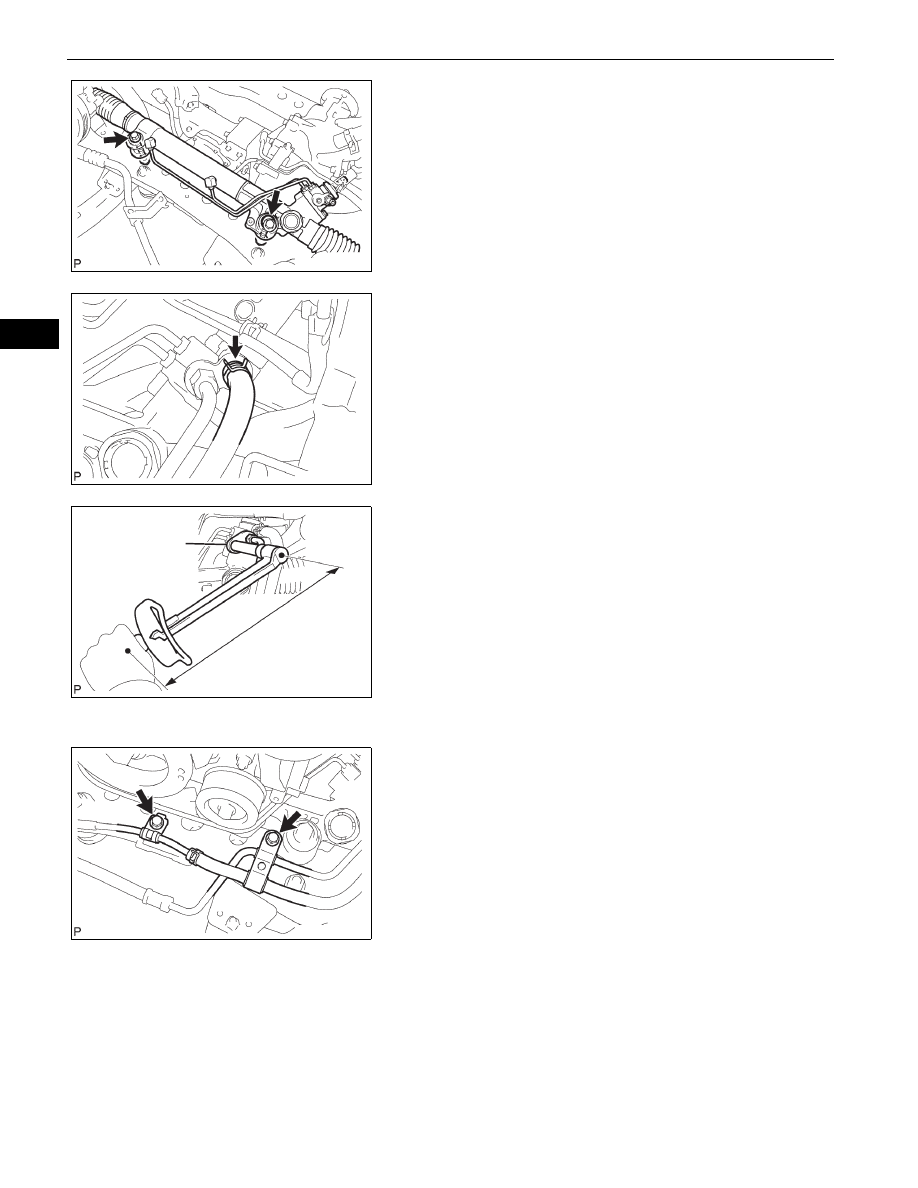
INSTALL POWER STEERING LINK
(a) Install the power steering link with the 2 bolts and 2 

nuts.
Torque: 100 N*m (1,020 kgf*cm, 74 ft.*lbf)
NOTICE:
Never turn the nut since it has a detent. Be sure 
to turn only the bolt.

2.

INSTALL PRESSURE FEED TUBE ASSEMBLY
(a) Connect the return hose with the clip.

(b) Using SST, tighten the flare nut and connect the 

pressure feed tube.
SST

09023-12701

Torque: for use without SST

44 N*m (449 kgf*cm, 33 ft.*lbf)
for use with SST
42 N*m (420 kgf*cm, 31 ft.*lbf)

HINT:

Use a torque wrench with a fulcrum length of 300 
mm (11.81 in.).

This torque value is effective when SST is 
parallel to the torque wrench.

(c) Install the tube support brackets with the 2 bolts.

Torque: 28 N*m (286 kgf*cm, 21 ft.*lbf)

F051684E01

F051683E01

Fulcrum Length

SST

F051698E01

F051681E01

POWER STEERING  –  POWER STEERING LINK (for 2WD)

PS–31

PS

3.

INSTALL COOLER COMPRESSOR ASSEMBLY
(a) Install the cooler compressor and magnetic clutch 

with the 4 bolts.

4.

INSTALL TIE ROD END SUB-ASSEMBLY LH
(a) Install the tie rod end onto the steering knuckle arm.
(b) Install the nut.

Torque: 91 N*m (928 kgf*cm, 67 ft.*lbf)

(c) Install a new cotter pin.

5.

INSTALL TIE ROD END SUB-ASSEMBLY RH
HINT:
The installation procedure for the RH side is the same as 
that for the LH side.

6.

INSTALL NO. 2 STEERING INTERMEDIATE SHAFT
(a) Align the matchmarks on the No. 2 steering 

intermediate shaft and power steering link.

(b) Install the No. 2 steering intermediate shaft onto the 

power steering link with bolt C.
Torque: 36 N*m (367 kgf*cm, 27 ft.*lbf)

(c) Align the matchmarks on the steering intermediate 

shaft and steering sliding yoke.

(d) Install the steering sliding yoke onto the steering 

intermediate shaft and slide it upward.

(e) Align the matchmarks on the steering sliding yoke 

and No. 2 steering intermediate shaft.

(f)

Install the steering sliding yoke with bolts A and B.
Torque: 36 N*m (367 kgf*cm, 27 ft.*lbf)

7.

REMOVE FAN AND GENERATOR V BELT (See page 

EM-6

)

8.

INSTALL FRONT WHEELS
Torque: 113 N*m (1,152 kgf*cm, 83 ft.*lbf)

9.

PLACE FRONT WHEELS FACING STRAIGHT AHEAD

10. INSPECT STEERING WHEEL CENTER POINT

11. CONNECT CABLE TO NEGATIVE BATTERY 

TERMINAL
Torque: 3.9 N*m (40 kgf*cm, 35 in.*lbf)

12. ADD POWER STEERING FLUID

13. BLEED POWER STEERING FLUID (See page 

PS-2

)

14. CHECK FOR POWER STEERING FLUID LEAKAGE

15. INSPECT AND ADJUST FRONT WHEEL ALIGNMENT

(See page 

SP-2

)

16. INSTALL NO. 1 ENGINE UNDER COVER SUB-

ASSEMBLY (See page 

EM-7

)

C133811

Matchmarks

C

F051678E02

A

B

Matchmarks

F051677E01

PS–32

POWER STEERING  –  POWER STEERING LINK (for 4WD)

PS

STEERING

POWER STEERING

POWER STEERING LINK (for 4WD)

COMPONENTS

REAR ENGINE UNDER 
COVER ASSEMBLY

FRONT EXHAUST PIPE ASSEMBLY

NO. 1 ENGINE UNDER 
COVER SUB-ASSEMBLY

N*m (kgf*cm, ft*lbf)  :Specified torque

Non-reusable part

29 (296, 21)

54 (554, 40)

48 (489, 35)

43 (438, 32)

x4

x4

GASKET

GASKET

GASKET

GASKET

COMPRESSION SPRING

COMPRESSION SPRING

x2

x2

43 (438, 32)

54 (554, 40)

29 (296, 21)

x2

NO. 2 FRONT EXHAUST PIPE ASSEMBLY

C133785E01

POWER STEERING  –  POWER STEERING LINK (for 4WD)

PS–33

PS

NO.3 FRAME CROSSMEMBER 
SUB-ASSEMBLY

EXHAUST PIPE STOPPER BRACKET

FRONT PROPELLER 
SHAFT ASSEMBLY

PROPELLER SHAFT ASSEMBLY

PROPELLER SHAFT 
HEAT INSULATOR

N*m (kgf*cm, ft*lbf)  :Specified torque

88 (899, 65)

19 (194, 14)

40 (408, 30)

88 (899, 65)

88 (899, 65)

88 (899, 65)

x4

x4

x4

x4

x2

x2

x2

16 (160, 12)

40 (408, 30)

FRONT SUSPENSION 
MEMBER BRACKET

FRONT SUSPENSION 
MEMBER BRACKET LH

33 (336, 24)

x4

x4

33 (336, 24)

C137987E01


Content   ..  368  369  370  371   ..