Toyota FJ Cruiser (GSJ 10, 15 series). Instruction - part 339


  Index      Toyota     Toyota FJ Cruiser (model GSJ 10, 15 series) - service repair instruction 2007 year


Search            copyright infringement  


Content   ..  337  338  339  340   ..


Toyota FJ Cruiser (GSJ 10, 15 series). Instruction - part 339


MI–12

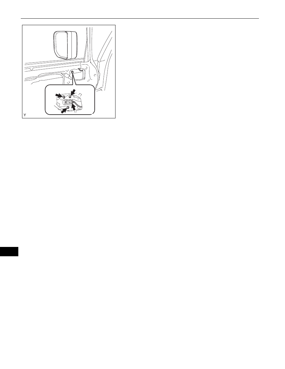
MIRROR  –  OUTER REAR VIEW MIRROR

MI

(b) Install the outer rear view mirror with the 3 bolts.

Torque: 8.0 N*m (82 kgf*cm, 71 in.*lbf)

(c) Connect the connector.

3.

INSTALL NO. 2 FRONT DOOR SERVICE HOLE 
COVER
HINT:
Use the same procedure as for the RH side (see page 

ED-24

).

4.

INSTALL FRONT DOOR TRIM BOARD SUB-
ASSEMBLY
HINT:
Use the same procedure as for the RH side (see page 

ED-24

).

5.

INSTALL FRONT ARMREST BASE UPPER PANEL 
(See page 

WS-27

)

6.

CONNECT CABLE TO NEGATIVE BATTERY 
TERMINAL
Torque: 3.9 N*m (40 kgf*cm, 35 in.*lbf)

B135564

MIRROR  –  OUTER MIRROR SWITCH

MI–13

MI

BODY

MIRROR

OUTER MIRROR SWITCH

COMPONENTS

FUSE BOX OPENING 
COVER

OUTER MIRROR 
SWITCH

B138152E01

MI–14

MIRROR  –  OUTER MIRROR SWITCH

MI

REMOVAL

1.

DISCONNECT CABLE FROM NEGATIVE BATTERY 
TERMINAL

2.

REMOVE FUSE BOX OPENING COVER
(a) Disengage the 4 claws and remove the fuse box 

opening cover.

3.

REMOVE OUTER MIRROR SWITCH
(a) Using a screwdriver with its tip wrapped in 

protective tape, disengage the 2 claws and remove 
the outer mirror switch.

(b) Disconnect the connector.

INSPECTION

1.

INSPECT OUTER MIRROR SWITCH
(a) Check the resistance.

(1) Select L on the left/right adjustment switch.
(2) Using an ohmmeter, measure the resistance 

and check the results in accordance with the 
value(s) in the table below.
Standard Resistance

If the result is not as specified, replace the 
outer mirror switch.

(3) Select R on the left/right adjustment switch.

B138155

Protective Tape

B138153E01

L R

MIRROR

1

2

3

4

5

6

7

8

9

10

B127217

Tester Connection

Condition

Specified Condition

4 (VL) - 7 (E)
4 (VL) - 8 (B)
5 (HL) - 7 (E)

5 (HL) - 8 (B)
6 (M+) - 7 (E)

6 (M+) - 8 (B)

OFF

10 k

 or higher

4 (VL) - 8 (B)

6 (M+) - 7 (E)

UP

Below 1 

4 (VL) - 7 (E)

6 (M+) - 8 (B)

DOWN

Below 1 

5 (HL) - 8 (B)
6 (M+) - 7 (E)

LEFT

Below 1 

5 (HL) - 7 (E)

6 (M+) - 8 (B)

RIGHT

Below 1 

MIRROR  –  OUTER MIRROR SWITCH

MI–15

MI

(4) Using an ohmmeter, measure the resistance 

and check the results in accordance with the 
value(s) in the table below.
Standard Resistance

If the result is not as specified, replace the 
outer mirror switch.

INSTALLATION

1.

INSTALL OUTER MIRROR SWITCH
(a) Connect the connector.
(b) Engage the 2 claws and install the outer mirror 

switch.

2.

INSTALL FUSE BOX OPENING COVER
(a) Engage the 4 claws and install the fuse box opening 

cover.

3.

CONNECT CABLE TO NEGATIVE BATTERY 
TERMINAL
Torque: 3.9 N*m (40 kgf*cm, 35 in.*lbf)

Tester Connection

Condition

Specified Condition

2 (HR) - 7 (E)
4 (HR) - 8 (B)
3 (VR) - 7 (E)
3 (VR) - 8 (B)
6 (M+) - 7 (E)
6 (M+) - 8 (B)

OFF

10 k

 or higher

3 (VR) - 8 (B)
6 (M+) - 7 (E)

UP

Below 1 

3 (VR) - 7 (E)

6 (M+) - 8 (B)

DOWN

Below 1 

2 (HR) - 8 (B)

6 (M+) - 7 (E)

LEFT

Below 1 

2 (HR) - 7 (E)
6 (M+) - 8 (B)

RIGHT

Below 1 

B138154

B138155


Content   ..  337  338  339  340   ..