Toyota FJ Cruiser (GSJ 10, 15 series). Instruction - part 340


  Index      Toyota     Toyota FJ Cruiser (model GSJ 10, 15 series) - service repair instruction 2007 year


Search            copyright infringement  


Content   ..  338  339  340  341   ..


Toyota FJ Cruiser (GSJ 10, 15 series). Instruction - part 340


MULTIPLEX COMMUNICATION  –  MULTIPLEX COMMUNICATION SYSTEM

MP–1

MP

MULTIPLEX COMMUNICATION 
SYSTEM

PRECAUTION

1.

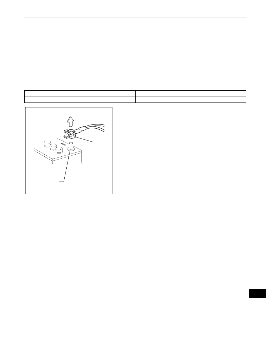
DISCONNECT AND RECONNECT CABLE OF 
NEGATIVE BATTERY TERMINAL
NOTICE:
When disconnecting the cable from the negative (-) 
battery terminal, initialize the following systems after 
the cable is reconnected.

(a) Before performing electronic work, disconnect the 

cable from the negative (-) battery terminal in order 
to prevent it from shorting and burning out.

(b) Before disconnecting and reconnecting the battery 

cable, turn the ignition switch OFF and the headlight 
dimmer switch OFF. Then loosen the terminal nut 
completely. Do not damage the cable or terminal.

(c) When the battery cable is disconnected, the clock 

and radio settings and stored DTCs are erased. 
Therefore, before disconnecting the battery cable, 
make a notes of them.

System Name

See procedure

METER / GAUGE SYSTEM

See page 

ME-10

Negative (-) 
Battery Terminal

Cable

D033496E01

MP–2

MULTIPLEX COMMUNICATION  –  MULTIPLEX COMMUNICATION SYSTEM

MP

PARTS LOCATION

Main Body ECU 
(Driver Side J/B)

Back Door ECU

B137551E01

MULTIPLEX COMMUNICATION  –  MULTIPLEX COMMUNICATION SYSTEM

MP–3

MP

SYSTEM DIAGRAM

POWER

Back Door ECU

Main Body ECU

J/B

ALT

Short 
Pin

ECU-B

Battery

BDR

BECU

GND

MPX2

MPX2

B137552E01

MP–4

MULTIPLEX COMMUNICATION  –  MULTIPLEX COMMUNICATION SYSTEM

MP

SYSTEM DESCRIPTION

1.

MULTIPLEX COMMUNICATION SYSTEM (BEAN)
(a) The BEAN communication line consists of 2 

systems: One is a system with a loop-shaped line 
that links the back door ECU with the main body 
ECU, which is located in the center of the line.
Since the line for the back door ECU is loop-
shaped, communication can be maintained by the 
line that is not open even if part of the line becomes 
open for some reason. In the case that there is a 
short-circuit (bus-down) in the line, however, all the 
BEAN communication becomes impossible in the 
system and some DTCs are output.
HINT:

When bus-down occurs, communication from the 
related ECU stops. Therefore, DTCs cannot be 
output, so perform a DTC (SAE code) inspection 
using the intelligent tester.

The back door ECU has a single communication 
line. Therefore, if the line has a short-circuit (bus-
down), the BEAN communication will be 
impossible and DTCs will not be output, either.

2.

CHECK COMMUNICATION FUNCTION
(a) Check the battery voltage.

Standard voltage:

11 to 14 V

(b) Inspect the DTC output.

(1) Check for DTCs concerning the main body ECU 

by connecting the intelligent tester to the DLC3 
and turning the ignition switch ON.

(2) When the display shows DTCs concerning the 

ECU being unconnected and the communication 
bus defective, perform the inspection depending 
on the troubleshooting procedures.
HINT:
When other DTCs are output, refer to the DTC 
table and check the applicable section.


Content   ..  338  339  340  341   ..