Toyota FJ Cruiser (GSJ 10, 15 series). Instruction - part 272


  Index      Toyota     Toyota FJ Cruiser (model GSJ 10, 15 series) - service repair instruction 2007 year


Search            copyright infringement  


Content   ..  270  271  272  273   ..


Toyota FJ Cruiser (GSJ 10, 15 series). Instruction - part 272


INTRODUCTION  –  HOW TO TROUBLESHOOT ECU CONTROLLED SYSTEMS

IN–43

IN

Do not apply heat directly to the parts in 
the ECU.

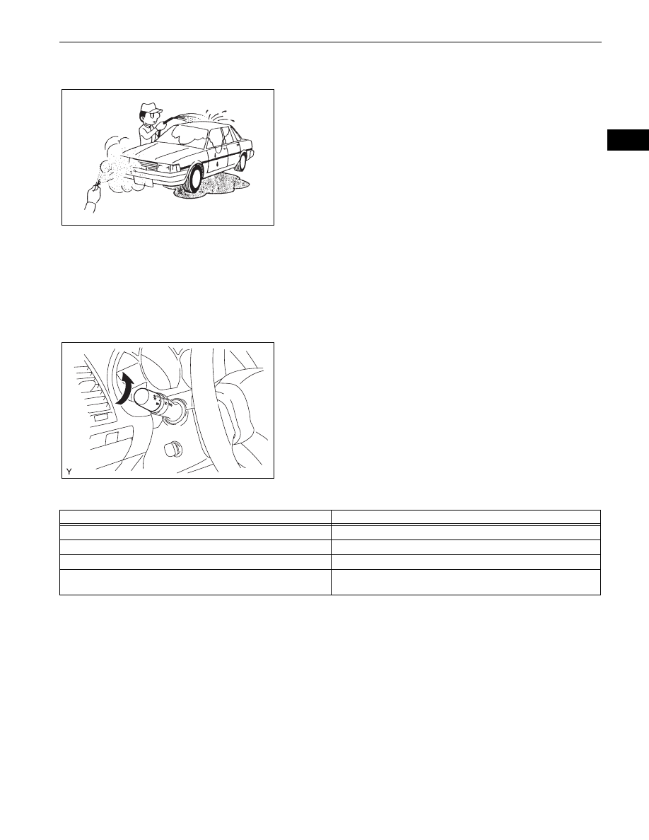
(c) WATER SPRINKLING METHOD:

When a malfunction seems to occur on a rainy day 
or in high-humidity.
(1) Sprinkle water onto the vehicle and check if the 

malfunction occurs.
NOTICE:

Never sprinkle water directly into the 
engine compartment. Indirectly change 
the temperature and humidity by spraying 
water onto the front of the radiator.

Never apply water directly onto the 
electronic components.

HINT:
If the vehicle has or had a water leakage 
problem, the leakage may have damaged the 
ECU or connections. Look for evidence of 
corrosion or short circuits. Proceed with caution 
during water tests.

(d) HIGH ELECTRICAL LOAD METHOD:

When a malfunction seems to occur when electrical 
load is excessive.
(1) Turn on the heater blower, headlight, rear 

window defogger and all other electrical loads. 
Check if the malfunction reoccurs.

5.

DIAGNOSTIC TROUBLE CODE CHART

Look for output Diagnostic Trouble Codes (DTCs) (from the 
DTC checks) in the appropriate section's Diagnostic Trouble 
Code Chart. Use the chart to determine the trouble area and 
the proper inspection procedure. A description of each of the 
chart's columns are below.

6.

PROBLEM SYMPTOMS TABLE
When a "Normal" code is output during a DTC check but 
the problem is still occurring, use the Problem Symptoms 
Table. The suspected areas (circuits or parts) for each 
problem symptom are in the table. The suspected areas 
are listed in order of probability. A description of each of 
the chart's columns are below.
HINT:
In some cases, the problem is not detected by the 
diagnostic system even though a problem symptom is 
present. It is possible that the problem is occurring 
outside the detection range of the diagnostic system, or 
that the problem is occurring in a completely different 
system.

D025085E02

AUTO

B107149

Item

Description

DTC No.

Indicates the diagnostic trouble code

Detection Item

Indicates the system or details of the problem

Trouble Area

Indicates the suspect areas of the problem

See Page

Indicates the page where the inspection procedures for each circuit is 
to be found, or gives instruction for checking and repairs.

IN–44

INTRODUCTION  –  HOW TO TROUBLESHOOT ECU CONTROLLED SYSTEMS

IN

7.

CIRCUIT INSPECTION
A description of the main areas of each circuit inspection 
is below.

Item

Description

Problem Symptom

-

Circuit Inspection, Inspection Order

Indicates the order in which the circuits need to be checked

Circuit or Part Name

Indicates the circuit or part which needs to be checked

See Page

Indicates the page where the flowchart for each circuit is located

Item

Description

Circuit Description

The major role, operation of the circuit and its component parts are 
explained.

Diagnostic Trouble Code No. and Detection Item

Indicates the diagnostic trouble codes, diagnostic trouble code 
settings and suspected areas for a problem

Wiring Diagram

This shows a wiring diagram of the circuit.
Use this diagram together with ELECTRICAL WIRING DIAGRAM to 
thoroughly understand the circuit.
Wire colors are indicated by an alphabetical code:

B  =  Black

L  =  Blue

R  =  Red

BR  =  Brown

LG = Light Green

V = Violet

G  =  Green

O = Orange

W  =  White

GR  =  Gray

P  =  Pink

Y  =  Yellow

SB = Sky Blue

The first letter indicates the basic wire color and the second letter 
indicates the color of the stripe.

Inspection Procedures

Use the inspection procedures to determine if the circuit is normal or 
abnormal. If abnormal, use the inspection procedures to determine 
whether the problem is located in the sensors, actuators, wire 
harnesses or ECU.

Indicates the condition of the connector of the ECU during the check

Connector being checked is connected.
Connections of tester are indicated by (+) or (-) after the terminal 
name.
Connector being checked is disconnected.
For illustrations of inspections between a connector and body ground, 
information about the body ground is not shown in the illustration.

INTRODUCTION  –  HOW TO TROUBLESHOOT ECU CONTROLLED SYSTEMS

IN–45

IN

ELECTRONIC CIRCUIT INSPECTION 
PROCEDURE

1.

BASIC INSPECTION
(a) WHEN MEASURING RESISTANCE OF 

ELECTRONIC PARTS
(1) Unless otherwise stated, all resistance 

measurements should be made at an ambient 
temperature of 20

°C (68°F). Resistance 

measurements may be inaccurate if measured 
at high temperatures, i.e. immediately after the 
vehicle has been running. Measurements should 
be made after the engine has cooled down.

(b) HANDLING CONNECTORS

(1) When disconnecting a connector, first squeeze 

the mating halves tightly together to release the 
lock, and then press the lock claw and separate 
the connector.

(2) When disconnecting a connector, do not pull on 

the harnesses. Grasp the connector directly and 
separate it.

(3) Before connecting a connector, check that there 

are no deformed, damaged, loose or missing 
terminals.

(4) When connecting a connector, press firmly until 

it locks with a "click" sound.

(5) If checking a connector with a TOYOTA 

electrical tester, check the connector from the 
backside (harness side) using a mini test lead.
NOTICE:

As a waterproof connector cannot be 
checked from the backside, check it by 
connecting a sub-harness.

Do not damage the terminals by moving 
the inserted tester needle.

(c) CHECKING CONNECTORS

(1) Checking when a connector is disconnected: 

Squeeze the connector together to confirm that 
they are fully connected and locked.

(2) Checking when a connector is disconnected: 

Check by pulling the wire harness lightly from 
the backside of the connector. Look for 
unlatched terminals, missing terminals, loose 
crimps or broken conductor wires. Check 
visually for corrosion, metallic or foreign matter 
and water, and bent, rusted, overheated, 
contaminated, or deformed terminals.

INCORRECT

INCORRECT

CORRECT

D032092E01

Core Wire

Terminal 
Deformation

Pull Lightly

Looseness of 
Crimping

D025087E03

IN–46

INTRODUCTION  –  HOW TO TROUBLESHOOT ECU CONTROLLED SYSTEMS

IN

(3) Checking the contact pressure of the terminal: 

Prepare a spare male terminal. Insert it into a 
female terminal, and check for ample tension 
when inserting and after full engagement.
NOTICE:
When testing a gold-plated female terminal, 
always use a gold-plated male terminal.

(d) REPAIR METHOD OF CONNECTOR TERMINAL

(1) If there is any foreign matter on the terminal, 

clean the contact point using an air gun or cloth. 
Never rub the contact point using sandpaper as 
the plating may come off.

(2) If there is abnormal contact pressure, replace 

the female terminal. If the male terminal is gold-
plated (gold color), use a gold-plated female 
terminal; if it is silver-plated (silver color), use a 
silver-plated female terminal.

(3) Damaged, deformed, or corroded terminals 

should be replaced. If the terminal does not lock 
into the housing, the housing may have to be 
replaced.

(e) HANDLING OF WIRE HARNESS

(1) If removing a wire harness, check the wiring and 

clamping before proceeding so that it can be 
restored in the same way.

(2) Never twist, pull or slacken the wire harness 

more than necessary.

(3) The wire harness should never come into 

contact with a high temperature part, or rotating, 
moving, vibrating or sharp-edged parts. Avoid 
contact with panel edges, screw tips and other 
sharp items.

(4) When installing parts, never pinch the wire 

harness.

(5) Never cut or break the cover of the wire harness. 

If it is cut or broken, replace it or repair it with 
vinyl tape.

2.

CHECK FOR OPEN CIRCUIT
(a) For an open circuit in the wire harness in Fig. 1, 

check the resistance or voltage, as described below.

D025088E02

CORRECT

INCORRECT

D032093E01

INCORRECT

INCORRECT

INCORRECT

D032094E01

Fig. 1

OPEN

ECU

B

SENSOR

A

C

1

2

2

2

2

1

1

1

Z017004E02


Content   ..  270  271  272  273   ..