Toyota FJ Cruiser (GSJ 10, 15 series). Instruction - part 270
IN–36
INTRODUCTION – REPAIR INSTRUCTION
IN
HINT:
•
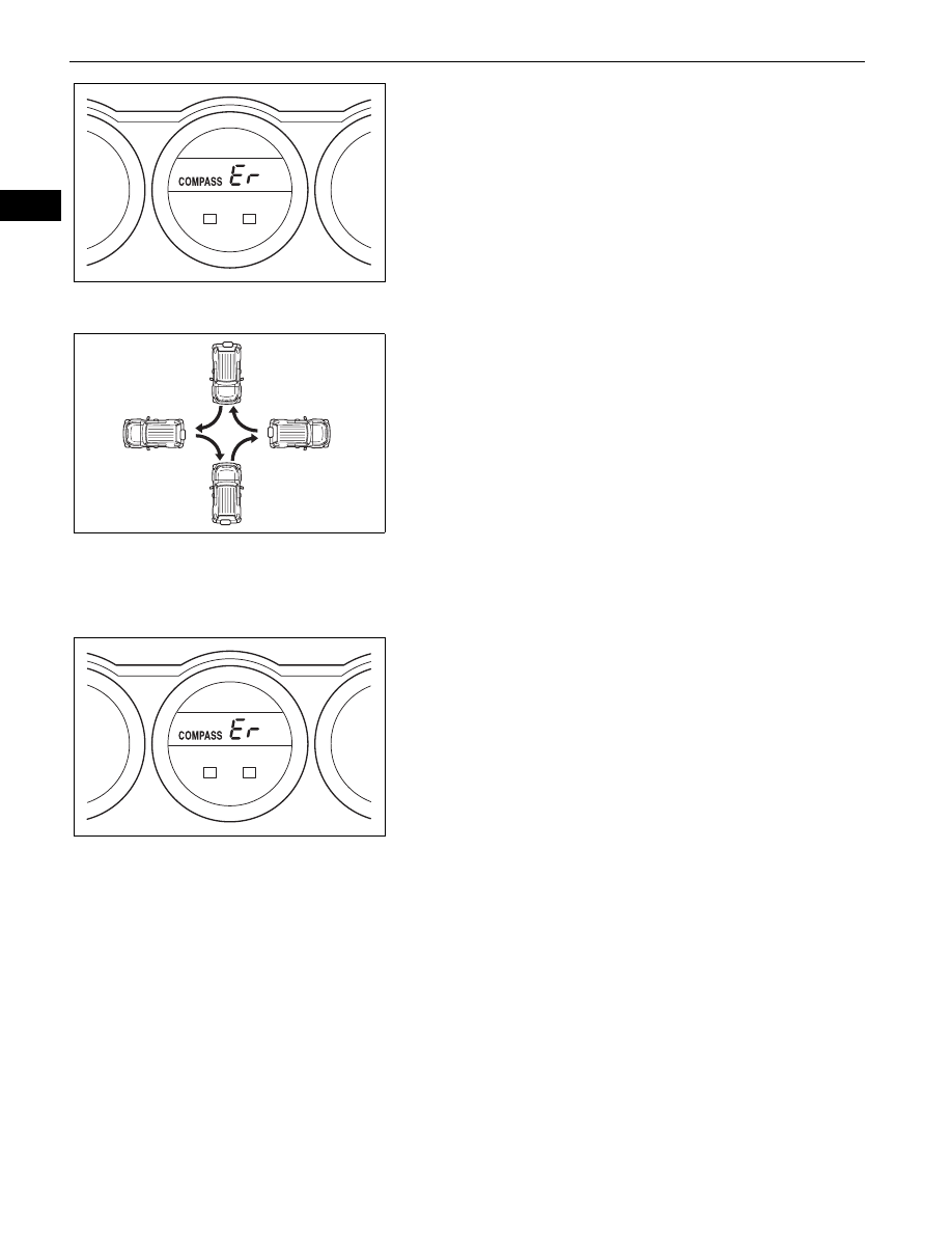
When the compass display returns to the
outside temperature display, the calibration is
complete.
•
When the circling calibration fails, "Er" is
displayed for about 2 seconds and then the
COMPASS indicator flashes.
•
If the correct direction is not displayed after
driving the vehicle as specified, change the
vehicle location.
•
To cancel the calibration before completion,
push the SET button for about 2 seconds.
(5) If enough space is not available to drive in a
circle, perform the following:
1. Perform a four-point turn within 2 minutes, as
shown in the illustration.
NOTICE:
•
Do not perform the circling calibration of
the compass in a place where the earth's
magnetic field is subject to interference by
artificial magnetic fields (underground
parking, under a steel tower, between
buildings, roof parking, near a crossing,
near a large vehicle, etc.).
•
During the calibration, do not operate any
electric systems (power window, etc.) as
they may interfere with the calibration.
HINT:
•
When the compass display returns to the
outside temperature display, the calibration is
complete.
•
When the circling calibration fails, "Er" is
displayed for about 2 seconds and then the
COMPASS indicator flashes.
•
If the correct direction is not displayed after
driving the vehicle as specified, change the
vehicle location.
•
To cancel the calibration before completion,
push the SET button for about 2 seconds.
(6) Check that the COMPASS indicator is not
blinking and that the compass is displayed
normally.
B133392
B133391
B133392