Toyota FJ Cruiser (GSJ 10, 15 series). Instruction - part 271


  Index      Toyota     Toyota FJ Cruiser (model GSJ 10, 15 series) - service repair instruction 2007 year


Search            copyright infringement  


Content   ..  269  270  271  272   ..


Toyota FJ Cruiser (GSJ 10, 15 series). Instruction - part 271


INTRODUCTION  –  HOW TO TROUBLESHOOT ECU CONTROLLED SYSTEMS

IN–39

IN

HINT:

In troubleshooting, confirm that the problem symptoms 
have been accurately identified. Preconceptions should be 
discarded in order to make an accurate judgment. To 
clearly understand what the problem symptoms are, it is 
extremely important to ask the customer about the 
problem and the conditions at the time the malfunction 
occurred.

Gather as much information as possible for reference. 
Past problems that seem unrelated may also help in some 
cases. 

The following 5 items are important points in the problem 
analysis:

3.

SYMPTOM CONFIRMATION AND DIAGNOSTIC 
TROUBLE CODE
HINT:
The diagnostic system in the FJ CRUISER has various 
functions.

The first function is the Diagnostic Trouble Code 
(DTC) check. A DTC is a code stored in the ECU 
memory whenever a malfunction in the signal circuits 
to the ECU occurs. In a DTC check, a previous 
malfunction's DTC can be checked by a technician 
during troubleshooting.

Another function is the Input Signal Check, which 
checks if the signals from various switches are sent to 
the ECU correctly.
By using these functions, the problem areas can be 
narrowed down and troubleshooting is more effective. 
Diagnostic functions are incorporated in the following 
system in the FJ CRUISER.
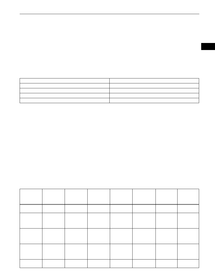
What

Vehicle model, system name

When

Date, time, occurrence frequency

Where

Road conditions

Under what conditions?

Running conditions, driving conditions, weather conditions

How did it happen?

Problem symptoms

System

DTC Check

(Normal Mode)

DTC Check

(Check Mode)

Freeze-frame 

Data

Sensor Check 

/ Test Mode 

(Input Signal 

Check)

Data List

Active Test

Customize 

Parameter

1GR-FE SFI 
SYSTEM

{

{

{

-

{

{

-

A750E 
AUTOMATIC 
TRANSAXLE 
SYSTEM

{

{

-

-

{

{

-

A750F 
AUTOMATIC 
TRANSAXLE 
SYSTEM

{

{

-

-

{

{

-

VEHICLE 
STABILITY 
CONTROL 
SYSTEM

{

-

{

{

{

{

-

AIRBAG 
SYSTEM

{

{

-

-

{

-

-

IN–40

INTRODUCTION  –  HOW TO TROUBLESHOOT ECU CONTROLLED SYSTEMS

IN

In the DTC check, it is very important to determine 
whether the problem indicated by the DTC is either: 1) 
still occurring, or 2) occurred in the past but has since 
returned to normal. In addition, the DTC should be 
compared to the problem symptom to see if they are 
related. For this reason, DTCs should be checked 
before and after confirmation of symptoms (i.e., 
whether or not problem symptoms exist) to determine 
current system conditions, as shown in the flowchart 
below.

Never skip the DTC check. Failing to check DTCs 
may, depending on the case, result in unnecessary 
troubleshooting for systems operating normally or 
lead to repairs not related to the problem. Follow the 
procedures listed in the flowchart in the correct order.

The following flowchart shows how to proceed with 
troubleshooting using the DTC check. Directions from 
the flowchart will indicate how to proceed either to 
DTC troubleshooting or to the troubleshooting of each 
problem symptom.

NEXT

NEXT

Result

OCCUPANT 
CLASSIFICATI
ON SYSTEM

{

-

-

-

{

-

-

CRUISE 
CONTROL 
SYSTEM

{

-

-

-

{

-

-

MULTIPLEX 
COMMUNICAT
ION

{

-

-

-

-

-

-

CAN 
COMMUNICAT
ION SYSTEM

{

-

-

-

-

-

-

System

DTC Check

(Normal Mode)

DTC Check

(Check Mode)

Freeze-frame 

Data

Sensor Check 

/ Test Mode 

(Input Signal 

Check)

Data List

Active Test

Customize 

Parameter

1

DTC CHECK

2

MAKE A NOTE OF DTCS DISPLAYED AND THEN CLEAR MEMORY

3

SYMPTOM CONFIRMATION

Result

Proceed to

No symptoms exist

A

Symptoms exist

B

INTRODUCTION  –  HOW TO TROUBLESHOOT ECU CONTROLLED SYSTEMS

IN–41

IN

B

A

NEXT

Result

B

A

Result

If a DTC was displayed in the initial DTC check, the problem 
may have occurred in a wire harness or connector in that 
circuit in the past. Check the wire harness and connectors.

B

A

The problem is still occurring in a place other than the 
diagnostic circuit (the DTC displayed first is either for a past 
problem or a secondary problem).
4.

SYMPTOM SIMULATION
HINT:
The most difficult case in troubleshooting is when no 
problem symptoms occur. In such a case, a thorough 
problem analysis must be carried out. A simulation of the 
same or similar conditions and environment in which the 
problem occurred in the customer's vehicle should be 
carried out. No matter how much skill or experience a 
technician has, troubleshooting without confirming the 
problem symptoms will lead to important repairs being 
overlooked and mistakes or delays.

Go to step 5

4

SIMULATION TEST USING SYMPTOM SIMULATION METHODS

5

DTC CHECK

Result

Proceed to

DTC is not output

A

DTC is output

B

TROUBLESHOOTING OF PROBLEM 
INDICATED BY DTC

6

SYMPTOM CONFIRMATION

Result

Proceed to

Symptoms exist

A

No symptoms exist

B

SYSTEM NORMAL

TROUBLESHOOTING OF EACH PROBLEM SYMPTOM

IN–42

INTRODUCTION  –  HOW TO TROUBLESHOOT ECU CONTROLLED SYSTEMS

IN

For example:

With a problem that only occurs when the engine is 
cold or as a result of vibration caused by the road 
during driving, the problem can never be 
determined if the symptoms are being checked on 
a stationary vehicle or on a vehicle with a warmed-
up engine. Vibration, heat or water penetration 
(moisture) is difficult to reproduce. The symptom 
simulation tests below are effective substitutes for 
the conditions and can be applied on a stationary 
vehicle. Important points in the symptom 
simulation test: 
In the symptom simulation test, the problem 
symptoms as well as the problem area or parts 
must be confirmed. First, narrow down the 
possible problem circuits according to the 
symptoms. Then, connect the tester and carry out 
the symptom simulation test, judging whether the 
circuit being tested is defective or normal. Also, 
confirm the problem symptoms at the same time. 
Refer to the problem symptoms table for each 
system to narrow down the possible causes.

(a) VIBRATION METHOD:

When a malfunction seems to occur as a result of 
vibration.
(1) PART AND SENSOR

Apply slight vibration with a finger to the part of 
the sensor suspected to be the cause of the 
problem, and check whether or not the 
malfunction occurs.
NOTICE:
Applying strong vibration to relays may open 
them.

(2) CONNECTORS

Slightly shake the connector vertically and 
horizontally.

(3) WIRE HARNESS

Slightly shake the wire harness vertically and 
horizontally. 
HINT:
The connector joint and fulcrum of the vibration 
are the major areas that should be checked 
thoroughly.

(b) HEAT METHOD:

When a malfunction seems to occur when the area 
in question is heated.
(1) Heat the component that is the possible cause of 

the malfunction with a hair dryer or similar 
device. Check if the malfunction occurs.
NOTICE:

Do not heat to more than 60

°C (140°F). 

Exceeding this temperature may damage 
components.

Vibrate Slightly

Vibrate Slightly

Shake Slightly

B071602E03


Content   ..  269  270  271  272   ..