Toyota FJ Cruiser (GSJ 10, 15 series). Instruction - part 265


  Index      Toyota     Toyota FJ Cruiser (model GSJ 10, 15 series) - service repair instruction 2007 year


Search            copyright infringement  


Content   ..  263  264  265  266   ..


Toyota FJ Cruiser (GSJ 10, 15 series). Instruction - part 265


IN–16

INTRODUCTION  –  REPAIR INSTRUCTION

IN

(6) When disposing of a vehicle or the airbag 

assembly unit by itself, the airbag should be 
deployed using SST before disposal. Activate 
the airbag in a safe place away from electrical 
noise.

(f)

FRONT SEAT SIDE AIRBAG ASSEMBLY
(1) Always place a removed or new front seat airbag 

assembly with the airbag inflation direction 
facing up.

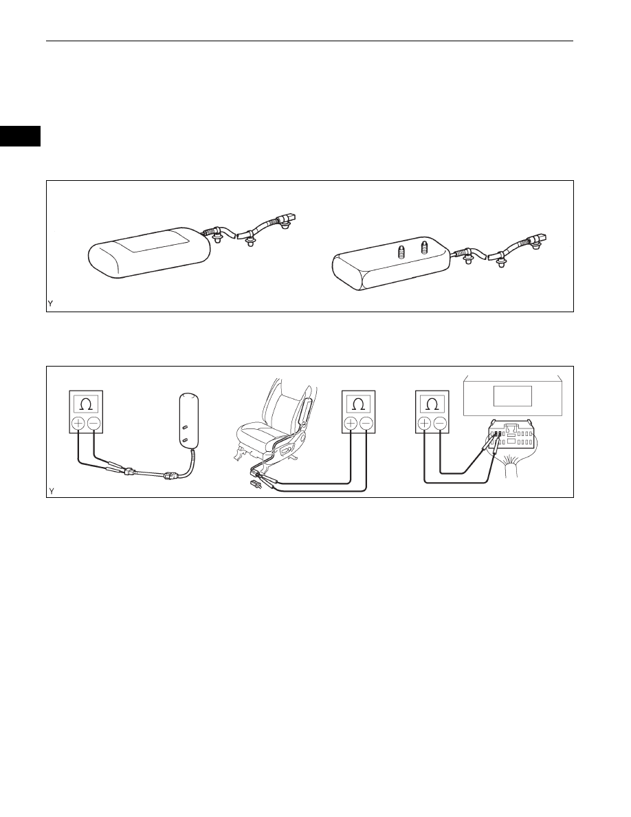
(2) Never measure the resistance of the airbag 

squib. This may cause the airbag to inflate, 
which could cause serious injury.

(3) Grease or detergents of any kind should not be 

applied to the front seat airbag assembly.

(4) Store the airbag assembly in an area where the 

ambient temperature is below 93

°C (200°F), the 

humidity is not high and there is no electrical 
noise.

(5) When using electric welding anywhere on the 

vehicle, disconnect the airbag ECU connectors 
(2 pins). These connectors contain shorting 
springs. This feature reduces the possibility of 
the airbag deploying due to currents entering the 
squib wiring.

(6) When disposing of a vehicle or the airbag 

assembly unit by itself, the airbag should be 
deployed using SST before disposal. Activate 
the airbag in a safe place away from electrical 
noise.

CORRECT

INCORRECT

Example:

D026601E01

Example:

D030924E02

INTRODUCTION  –  REPAIR INSTRUCTION

IN–17

IN

(g) FRONT SEAT OUTER BELT ASSEMBLY WITH 

PRETENSIONER
(1) Never measure the resistance of the seat outer 

belt. This may cause the pretensioner of the seat 
belt to activate, which could cause serious injury.

(2) Never disassemble the seat outer belt.
(3) Never install the seat outer belt on another 

vehicle.

(4) Store the seat outer belt in an area where the 

ambient temperature is below 80

°C (176°F), the 

humidity is not high and there is no electrical 
noise.

(5) When using electric welding anywhere on the 

vehicle, disconnect the airbag ECU connectors 
(2 pins). These connectors contain shorting 
springs. This feature reduces the possibility of 
the pretensioner deploying due to currents 
entering the squib wiring.

(6) When disposing of a vehicle or the seat outer 

belt assembly by itself, the seat outer belt should 
be activated before disposal. Activate it in a safe 
place away from electrical noise.

(7) As the seat outer belt is hot after the 

pretensioner is activated, allow some time for it 
to cool down sufficiently before disposal. Never 
apply water to try to cool down the seat outer 
belt.

(8) Grease, detergents, oil or water should not be 

applied to the front seat outer belt.

(h) AIRBAG SENSOR ASSEMBLY

(1) Never reuse an airbag sensor assembly that has 

been involved in a collision where the SRS has 
deployed.

(2) The connectors to the airbag sensor assembly 

should be connected or disconnected with the 
sensor placed on the floor. If the connectors are 
connected or disconnected while the airbag 
sensor assembly is not placed on the floor, the 
SRS may activate.

(3) Work must be started at least 90 seconds after 

the ignition switch is turned OFF and the cable is 
disconnected from the negative (-) battery 
terminal, even if only loosening the set bolts of 
the airbag sensor assembly.

Example:

D030370E02

IN–18

INTRODUCTION  –  REPAIR INSTRUCTION

IN

(i)

WIRE HARNESS AND CONNECTOR
(1) The SRS wire harness is integrated with the 

instrument panel wire harness assembly. All the 
connectors in the system are a standard yellow 
color. If the SRS wire harness becomes 
disconnected or the connector becomes broken, 
repair or replace it.

3.

ELECTRONIC CONTROL
(a) REMOVAL AND INSTALLATION OF BATTERY 

TERMINAL
NOTICE:
Certain systems need to be initialized after 
disconnecting and reconnecting the cable from 
the negative (-) battery terminal.
(1) Before performing electronic work, disconnect 

the cable from the negative (-) battery terminal to 
prevent component and wire damage caused by 
accidental short circuits.

(2) When disconnecting the cable, turn the ignition 

switch off and the headlight dimmer switch OFF 
and loosen the cable nut completely. Perform 
these operations without twisting or prying the 
cable. Then disconnect the cable.

(3) Clock settings, radio settings, audio system 

memory, DTCs and other data are erased when 
the cable is disconnected from the negative (-) 
battery terminal. Write down any necessary data 
before disconnecting the cable.

(b) HANDLING OF ELECTRONIC PARTS

(1) Do not open the cover or case of the ECU 

unless absolutely necessary. If the IC terminals 
are touched, the IC may be rendered inoperative 
by static electricity.

(2) Do not pull the wires when disconnecting 

electronic connectors. Pull the connector.

(3) Be careful not to drop electronic components, 

such as sensors or relays. If they are dropped 
on a hard surface, they should be replaced.

(4) When cleaning the engine with steam, protect 

the electronic components, air filter and 
emission-related components from water.

(5) Never use an impact wrench to remove or install 

temperature switches or temperature sensors.

(6) When measuring the resistance of a wire 

connector, insert the tester probe carefully to 
prevent terminals from bending.

4.

REMOVAL AND INSTALLATION OF FUEL CONTROL 
PARTS
(a) PLACE FOR REMOVING AND INSTALLING FUEL 

SYSTEM PARTS
(1) Work in a location with good air ventilation that 

does not have welders, grinders, drills, electric 
motors, stoves, or any other ignition sources.

Negative (-)
Cable

Negative (-)
Battery Terminal

D033608E02

INCORRECT

D031751E01

INTRODUCTION  –  REPAIR INSTRUCTION

IN–19

IN

(2) Never work in a pit or near a pit as vaporized 

fuel will collect in those places.

(b) REMOVING AND INSTALLING FUEL SYSTEM 

PARTS
(1) Prepare a fire extinguisher before starting the 

operation.

(2) To prevent static electricity, install a ground wire 

to the fuel changer, vehicle and fuel tank, and do 
not spray the surrounding area with water. Be 
careful when performing work in this area, as the 
work surface will become slippery. Do not clean 
up gasoline spills with water, as this may cause 
the gasoline to spread, and possibly create a fire 
hazard.

(3) Avoid using electric motors, working lights and 

other electric equipment that can cause sparks 
or high temperatures.

(4) Avoid using iron hammers as they may create 

sparks.

(5) Dispose of fuel-contaminated cloth separately 

using a fire resistant container.

5.

REMOVAL AND INSTALLATION OF ENGINE INTAKE 
PARTS
(a) If any metal particles enter inlet system parts, they 

may damage the engine.

(b) When removing and installing inlet system parts, 

cover the openings of the removed parts and engine 
openings. Use gummed tape or other suitable 
materials.

(c) When installing inlet system parts, check that no 

metal particles have entered the engine or the 
installed parts.

6.

HANDLING OF HOSE CLAMPS
(a) Before removing the hose, check the clamp position 

so that it can be reinstalled in the same position.

(b) Replace any deformed or dented clamps with new 

ones.

(c) When reusing a hose, attach the clamp on the 

clamp track portion of the hose.

(d) For a spring type clamp, you may want to spread 

the tabs slightly after installation by pushing in the 
direction of the arrows as shown in the illustration.

7.

FOR VEHICLES EQUIPPED WITH MOBILE 
COMMUNICATION SYSTEMS
(a) Install the antenna as far away from the ECU and 

sensors of the vehicle electronic systems as 
possible.

(b) Install an antenna feeder at least 20 cm (7.87 in.) 

away from the ECU and sensors of the vehicle 
electronic systems. For details about ECU and 
sensor locations, refer to the section of the 
applicable components.

D001563E01

Spring Type Clamp

Clamp Track

B107182E01

D020025E01


Content   ..  263  264  265  266   ..