Toyota FJ Cruiser (GSJ 10, 15 series). Instruction - part 263
IN–8
INTRODUCTION – REPAIR INSTRUCTION
IN
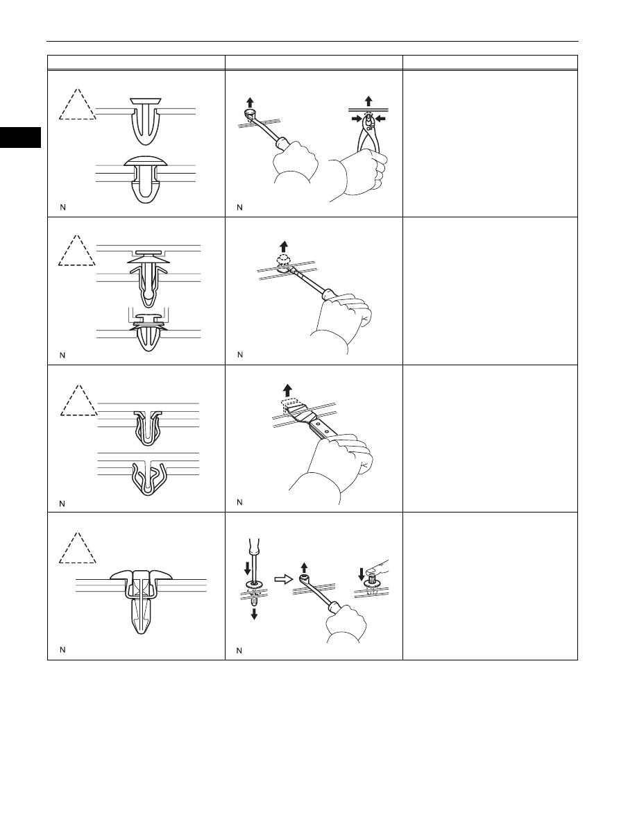
Shape (Example)
Illustration
Procedures
1.
Remove the clips with a clip remover or
pliers.
1.
Remove the clips with a clip remover or
screwdriver.
1.
Remove the clips with a wide scraper to
prevent panel damage.
1.
Remove the clips by pushing the center
pin through and prying out the shell.