Toyota FJ Cruiser (GSJ 10, 15 series). Instruction - part 247
 

  Index      Toyota     Toyota FJ Cruiser (model GSJ 10, 15 series) - service repair instruction 2007 year


Search            copyright infringement  


Content   ..  245  246  247  248   ..


Toyota FJ Cruiser (GSJ 10, 15 series). Instruction - part 247


INSTRUMENT PANEL  –  INSTRUMENT PANEL ASSEMBLY

IP–31

IP

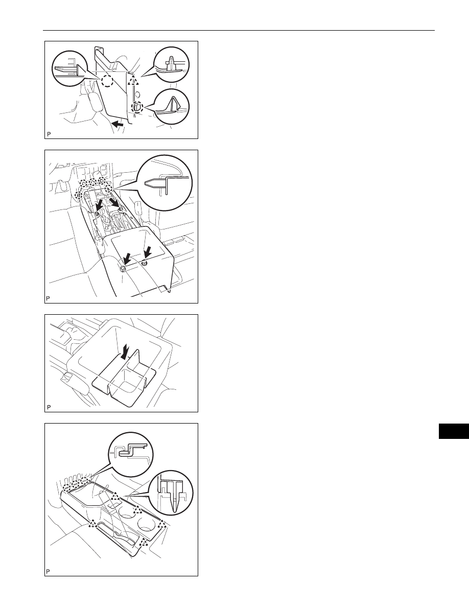
36. INSTALL CONSOLE UPPER PANEL NO. 1 GARNISH

(a) Slide the console upper panel garnish toward the 

front of the vehicle and engage claw B.

(b) Engage the claw and clip and install the console 

upper panel garnish.

37. INSTALL FRONT CONSOLE BOX

(a) Engage the 5 claws and install the front console 

box.

(b) Install the 4 <D> screws.

38. INSTALL BOX BOTTOM MAT

(a) Install the box bottom mat.

39. INSTALL CONSOLE UPPER REAR PANEL SUB-

ASSEMBLY
(a) Engage the 3 claws and 5 clips and install the 

console upper rear panel.

Claw B

Claw A

Clip

B133902E01

B133851

B133899

B133897

IP–32

INSTRUMENT PANEL  –  INSTRUMENT PANEL ASSEMBLY

IP

40. INSTALL SHIFT LEVER KNOB SUB-ASSEMBLY (for 

4WD)
(a) Install the shift lever knob.

41. INSTALL SHIFT LEVER KNOB SUB-ASSEMBLY (for 

Manual Transmission)
(a) Install the shift lever knob.

42. INSTALL PARKING BRAKE HOLE COVER SUB-

ASSEMBLY
(a) Slide the parking brake hole cover toward the rear 

of the vehicle and engage the 2 C claws.

(b) Engage the 4 claws and install the parking brake 

hole cover.

43. INSTALL RADIO RECEIVER ASSEMBLY (See page 

AV-56

)

44. INSTALL INTEGRATION CONTROL AND PANEL 

ASSEMBLY
(a) Connect the 3 connectors.
(b) Engage the 4 clips and install the integration control 

panel assembly.

(c) Install the 2 <H> screws.

B133896

B133894

Claw A

Claw C

Claw B

B133901E01

B133888

INSTRUMENT PANEL  –  INSTRUMENT PANEL ASSEMBLY

IP–33

IP

45. INSTALL INSTRUMENT PANEL GARNISH LH

(a) Engage the 3 clips and install the instrument panel 

garnish.

(b) Install 2 <H> screws.

46. INSTALL INSTRUMENT PANEL GARNISH RH

(a) Engage the 3 clips and install the instrument panel 

garnish.

(b) Install screw <H>.

47. INSTALL FRONT PILLAR GARNISH RH (See page 

IR-

43

)

48. INSTALL FRONT PILLAR GARNISH LH (See page 

IR-

43

)

49. INSTALL ASSIST GRIP ASSEMBLY (See page 

IR-43

)

50. INSTALL ASSIST GRIP PLUG (See page 

IR-44

)

51. INSTALL FRONT DOOR OPENING TRIM 

WEATHERSTRIP LH
(a) Install the front door opening trim weatherstrip.

52. INSTALL FRONT DOOR OPENING TRIM 

WEATHERSTRIP RH
(a) Install the front door opening trim weatherstrip.

53. INSTALL COWL SIDE TRIM BOARD RH (See page 

IR-

45

)

54. INSTALL COWL SIDE TRIM BOARD LH (See page 

IR-

45

)

55. INSTALL FOOTREST CLIP (See page 

IR-2

)

56. INSTALL FRONT FLOOR FOOTREST (See page 

IR-2

)

57. INSTALL FRONT DOOR SCUFF PLATE RH (See page 

IR-45

)

58. INSTALL FRONT DOOR SCUFF PLATE LH (See page 

IR-45

)

59. CONNECT CABLE TO NEGATIVE BATTERY 

TERMINAL
Torque: 3.9 N*m (40 kgf*cm, 35 in.*lbf)

60. INSPECT SRS WARNING LIGHT

(See page 

RS-29

)

B133886

B133887

1GR-FE INTAKE  –  INTAKE SYSTEM

IT–1

IT

ENGINE

1GR-FE INTAKE

INTAKE SYSTEM

PARTS LOCATION

INTAKE MANIFOLD

VACUUM SWITCHING VALVE

ECM

ENGINE ROOM RELAY BLOCK

EFI RELAY

-

- INTAKE AIR CONTROL VALVE

A126470E01


Content   ..  245  246  247  248   ..