Toyota FJ Cruiser (GSJ 10, 15 series). Instruction - part 246


  Index      Toyota     Toyota FJ Cruiser (model GSJ 10, 15 series) - service repair instruction 2007 year


Search            copyright infringement  


Content   ..  244  245  246  247   ..


Toyota FJ Cruiser (GSJ 10, 15 series). Instruction - part 246


INSTRUMENT PANEL  –  INSTRUMENT PANEL ASSEMBLY

IP–27

IP

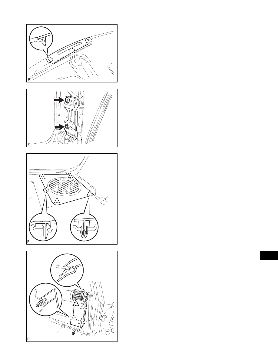
20. INSTALL INSTRUMENT PANEL FINISH PANEL END 

LH
(a) Engage the 3 claws and install the instrument panel 

finish panel end.

21. INSTALL ASSIST GRIP RETAINER RH

(a) Install the assist grip retainer with the 2 bolts.

Torque: 29 N*m (296 kgf*cm, 21 ft.*lbf)

22. INSTALL ASSIST GRIP RETAINER LH

HINT:
Use the same procedure as for the RH side.

23. INSTALL FRONT NO. 2 SPEAKER ASSEMBLY (See 

page 

AV-62

)

24. INSTALL NO. 2 INSTRUMENT PANEL SPEAKER 

PANEL SUB-ASSEMBLY
(a) Engage the 4 clips and claw and install the 

instrument panel speaker panel.

25. INSTALL NO. 1 INSTRUMENT PANEL SPEAKER 

PANEL SUB-ASSEMBLY
HINT:
Use the same procedure as for the RH side.

26. INSTALL NO. 2 INSTRUMENT PANEL REGISTER 

ASSEMBLY
(a) Engage the 4 clips and 2 claws and install the 

instrument panel register.

(b) Install the clip.

B133889

B133881

B133865

B133858

IP–28

INSTRUMENT PANEL  –  INSTRUMENT PANEL ASSEMBLY

IP

27. INSTALL INSTRUMENT PANEL LOWER FINISH 

PANEL SUB-ASSEMBLY RH
(a) Install the connectors to the instrument panel lower 

finish panel.

(b) Engage the claw and 2 clips and install the 

instrument panel lower finish panel.

(c) Install screw <A>.

28. INSTALL GLOVE COMPARTMENT DOOR ASSEMBLY

(a) Install the glove compartment door assembly with 

the 3 hinges while holding it horizontal.

(b) Slightly flex the upper part of the glove compartment 

door assembly, and install the glove compartment 
door assembly.

(c) Install the glove compartment door stoppers onto 

the glove compartment door.

29. INSTALL COMBINATION METER ASSEMBLY

(a) Connect the 2 connectors and the clamp.

B133857

B133856

2 Stoppers

B133854E01

B133863

INSTRUMENT PANEL  –  INSTRUMENT PANEL ASSEMBLY

IP–29

IP

(b) Install the combination meter assembly with the 4 

screws.
Torque: 7.0 N*m (71 kgf*cm, 62 in.*lbf)

30. INSTALL INSTRUMENT CLUSTER LOWER FINISH 

PANEL
(a) Connect the connectors.
(b) Engage the 3 clips and 4 claws and install the 

instrument cluster lower finish panel.

31. INSTALL LOWER INSTRUMENT PANEL LH

(a) Install the lower instrument panel with the 4 <F> 

bolts.

32. INSTALL LOWER INSTRUMENT PANEL FINISH 

PANEL SUB-ASSEMBLY LH
(a) Engage the 5 clips and claw and install the lower 

instrument panel finish panel.

(b) Install the 2 <F> bolts.

B133862

B133861

B133864

B133860

IP–30

INSTRUMENT PANEL  –  INSTRUMENT PANEL ASSEMBLY

IP

33. CONNECT HOOD LOCK CONTROL LEVER SUB-

ASSEMBLY
(a) Engage the 3 claws and install the hood lock control 

lever.

34. INSTALL NO. 1 INSTRUMENT PANEL REGISTER 

ASSEMBLY
(a) Engage the 4 clips and 2 claws and install the 

instrument panel register.

35. INSTALL INSTRUMENT LOWER COVER SUB-

ASSEMBLY
(a) Engage the 3 clips and 2 claws and install the 

instrument lower cover.

(b) Install the 2 <F> bolts and 2 clips.

B133859

B133853

B133852


Content   ..  244  245  246  247   ..