Toyota FJ Cruiser (GSJ 10, 15 series). Instruction - part 242


  Index      Toyota     Toyota FJ Cruiser (model GSJ 10, 15 series) - service repair instruction 2007 year


Search            copyright infringement  


Content   ..  240  241  242  243   ..


Toyota FJ Cruiser (GSJ 10, 15 series). Instruction - part 242


INSTRUMENT PANEL  –  INSTRUMENT PANEL ASSEMBLY

IP–11

IP

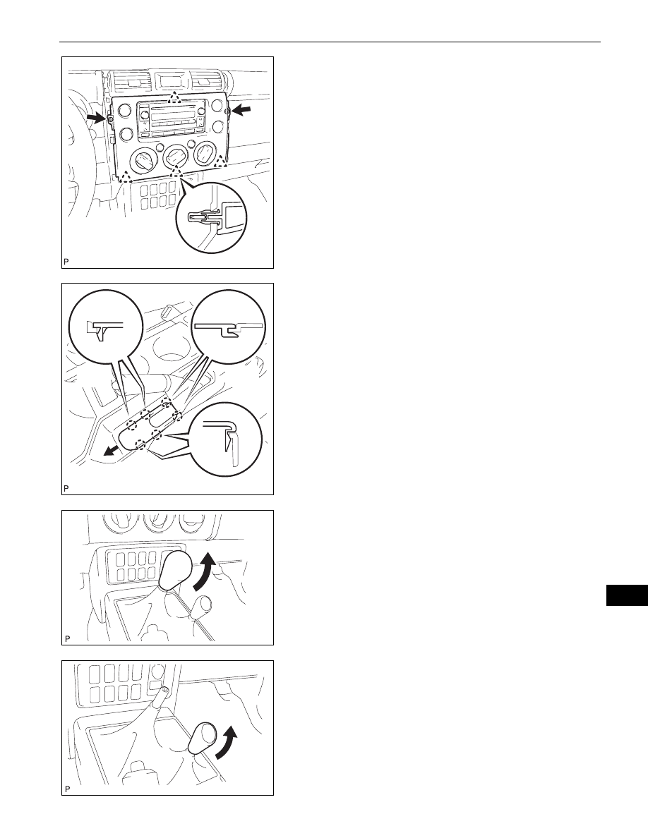
17. REMOVE INTEGRATION CONTROL AND PANEL 

ASSEMBLY
(a) Remove the 2 <H> screws.
(b) Disengage the 4 clips and remove the integration 

control panel assembly.

(c) Disconnect the 3 connectors.

18. REMOVE RADIO RECEIVER ASSEMBLY (See page 

AV-55

)

19. REMOVE PARKING BRAKE HOLE COVER SUB-

ASSEMBLY
(a) Disengage the 2 A claws and 2 B claws.
(b) Slide the parking brake hole cover toward the front 

of the vehicle, disengage the 2 C claws and remove 
the parking brake hole cover.

20. REMOVE SHIFT LEVER KNOB SUB-ASSEMBLY (for 

Manual Transmission)
(a) Remove the shift lever knob.

21. REMOVE SHIFT LEVER KNOB SUB-ASSEMBLY (for 

4WD)
(a) Remove the shift lever knob.

B133888

Claw A

Claw C

Claw B

B133898E02

B133893

B133895

IP–12

INSTRUMENT PANEL  –  INSTRUMENT PANEL ASSEMBLY

IP

22. REMOVE CONSOLE UPPER REAR PANEL SUB-

ASSEMBLY
(a) Shift the shift lever into the N position.
(b) Disengage the 5 clips and 3 claws and remove the 

console upper rear panel.

23. REMOVE BOX BOTTOM MAT

(a) Remove the box bottom mat.

24. REMOVE FRONT CONSOLE BOX

(a) Remove the 4 <D> bolts.
(b) Disengage the 5 claws and remove the console box.

25. REMOVE CONSOLE UPPER PANEL NO. 1 GARNISH

(a) Disengage claw A and the clip.
(b) Slide the console upper panel garnish toward the 

rear of the vehicle, disengage the claw B and 
remove the console upper panel garnish.

B133897

B133899

B133851

Claw B

Claw A

Clip

B133900E01

INSTRUMENT PANEL  –  INSTRUMENT PANEL ASSEMBLY

IP–13

IP

26. REMOVE INSTRUMENT LOWER COVER SUB-

ASSEMBLY
(a) Remove the 2 clips and 2 <F> bolts.
(b) Disengage the 3 clips and 2 claws and remove the 

instrument lower cover.

27. REMOVE NO. 1 INSTRUMENT PANEL REGISTER 

ASSEMBLY
(a) Disengage the 4 clips and 2 claws and remove the 

instrument panel register.
NOTICE:

To avoid breakage of the register, remove the 
instrument panel register with the shut 
damper of the register open.

Pull the instrument panel register up 
diagonally to remove it.

28. SEPARATE HOOD LOCK CONTROL LEVER SUB-

ASSEMBLY
(a) Disengage the 3 claws and separate the hood lock 

control lever.

B133852

B133853

B133859

IP–14

INSTRUMENT PANEL  –  INSTRUMENT PANEL ASSEMBLY

IP

29. REMOVE LOWER INSTRUMENT PANEL FINISH 

PANEL SUB-ASSEMBLY LH
(a) Remove the 2 <F> bolts.
(b) Disengage the 5 clips and claw and remove the 

lower instrument panel finish panel.

30. REMOVE LOWER INSTRUMENT PANEL LH

(a) Remove the 4 <F> bolts and remove the lower 

instrument panel.

31. REMOVE INSTRUMENT CLUSTER FINISH PANEL

(a) Disengage the 3 clips and the 4 claws and remove 

the instrument cluster finish panel.

(b) Disconnect the connectors.

32. REMOVE COMBINATION METER ASSEMBLY

(a) Remove the 4 screws.

B133860

B133864

B133861

B133862


Content   ..  240  241  242  243   ..